Magnetometer / Compass
These notes only apply to Magnetometers in Betaflight 4.5 or higher
Do NOT use a magnetometer unless you have confirmed that:
- the magnetometer's axes are correctly oriented
- the calibration is accurate
- the returned values are clean and noise-free
- the correct local declination angle is entered in the CLI
- the heading returned by the mag is correct
- Acc is enabled, correctly oriented, and calibrated
- GPS is included in the firmware, and enabled, to see the heading data
Introduction
A magnetometer is a 3D electronic compass, returning magnetic field strength in 3 orthogonal axes. Magnetometer data is used to estimate the 'heading' of the quad, meaning the angle in degrees between the nose of the quad and "true North". When set up correctly, the returned value should, for example, be 90° when the nose of the quad is pointing due East, 180° when pointing due South, etc.
Mag information improves behavior in GPS Rescue during the climb and descend phases, where wind and drift can confuse a GPS-only heading. It essential for accurate position hold, which we will support later.
The Mag heading is shown numerically in Configurator on the main Setup screen, in the GPS tab, and graphically over the Map in the GPS tab.
Summary
- please read all of this document before using a magnetometer (3D compass)
- the firmware must be custom built to include Mag support
- the magnetometer must power up at the same time as the flight controller
- the CLI
statuscommand must show the correct hardware as being connected - the magnetometer must be oriented correctly, and the orientation must be checked
- the magnetometer must be calibrated accurately
- the local declination angle must be set in the CLI
- the mag heading must be checked in Configurator, and compared to values reported from the compass of a mobile phone.
- the user must confirm that the reported heading is correct while in flight, from mag alone, during test flights (enable Mag, disable GPS and show heading in the OSD)
- the user must get GPS Rescue working properly, without Mag, before enabling the Mag
- the user must make careful tests of GPS Rescue after later adding Mag. With Mag, the initial rotation/climb phase, and the descent phase, should show more accurate heading control, especially in windy conditions. If it makes no difference to the rescue, or causes problems, don't use Mag.
DO NOT enable Mag if you rely on GPS rescue, until you are ABSOLUTELY CERTAIN that the Mag data is accurate and reliable!
What is a Magnetometer?
A magnetometer is a three-axis device that detects the strength and direction of the local magnetic field1.
Magnetometer sensors output data on three mutually perpendicular axes: X, Y and Z. The axes are typically configured so that if Z is up, and X is forward, Y points left. This is true for the popular QMC5883L. However, some magnetometers orient the axes differently.
When one of the Mag sensor's three axes points directly parallel and to the North of a magnetic field line, that axis returns its most positive value, and the other two axes return zero. Conversely, when pointing in the opposite direction, ie to the South end of the field, the same axis returns its most negative value, and the other two axes return zero. These raw values can be shown in the Sensors tab using the MAG_CALIB debug, and this is how the user can check the orientation of the axes of their module.
The orientation of the magnetometer on the quad is very important. In Betaflight, the data from the magnetometer must be returned as follows:
- X must point forward
- Y must point left
- Z must point up
Always use the Sensors tab to confirm that the sensor orientation is correct. If the Mag is an IST8310, its non-compliant Y axis orientation must be corrected with a custom configuration that rotates the Y axis by 180°.
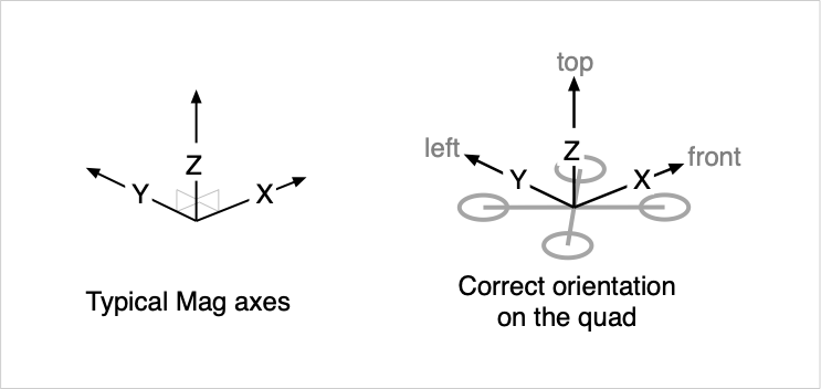 Fig. 1 - Magnetometer axes and orientation in relation to the drone as expected by Betaflight.
About the Earth's Magnetic Field
The earth's magnetic field1 is not uniform. Its field lines usually point a few degrees away from geographic North and either down (in the Northern Hemisphere) or up (in the Southern Hemisphere). Both the field direction and strength vary from place to place.
The earth's magnetic field is usually represented in a NED (north-east-down) frame of reference. This means that the X axis of the earth's field points North, the Y axis points East, and the Z axis points Down. This representation is not at all relevant for Betaflight's mag orientation, but may be useful when interpreting the magnetic field strength and direction values reported for your location.
The absolute strength of the field is measured in Gauss, or milliTeslas, where 1.0 Gauss = 0.1 milliTesla. In my location, the field strength is approximately 0.57 Gauss. Betaflight's sensors tab shows the values reported by the sensor, and these depend on the sensor gain, which can be found in the specification sheet. For example, the QMC5883L returns a value of 3000 for a field strength of 1 Gauss, so that in Sydney I would expect to get a value 1710 when that sensor, after calibration, was aligned directly into the field.
When we measure the magnetic field at a particular point on earth, we are measuring a local field vector which usually points a few degrees away from geographic North, and either down into the ground in the Northern Hemisphere, or up out of the ground in the Southern Hemisphere. There are considerable angular deviations, especially in the up or down angle, depending upon where you are on the surface of the Earth.
The sideways deviation of the Earth's magnetic field from the geographic north is called the magnetic declination. It is measured in degrees, with positive values meaning that the magnetic North is to the East of the geographic North.
The angle at which the field points into (or out of) the Earth's surface is called the magnetic inclination, or magnetic dip. See physicsmax.com2 for a nice explanation and graphic. Inclination is measured in degrees 'into' the ground. In the Northern Hemisphere the Earth's magnetic field points down into the ground (positive Inclination values), and in the Southern Hemisphere it points up into the sky (negative Inclination values).
Local Declination and Inclination values are available from online sources such as NOAA3, or via clickable map at sites like magnetic-declination.com4.
As an example, in Sydney, Australia, 151°E 34°S, the Earth's magnetic field is 13° east of geographic North, and steeply upwards out of the ground, at 65°. In other words, the Declination is 13° and the Inclination is -65°. If the Mag is oriented correctly, I should get a maximallly positive value on the Mag X axis, and close to zero on the Y and Z axes, when the nose of my quad is pointed 13° East of North, and 65°s up.
Setting local declination in the CLI
In Betaflight 4.5, the CLI variable mag_declination was introduced, to correct for declination offsets. When correctly set, Betaflight will return "true North", not "magnetic North", like the GPS course over ground values, which also return true North.
Declination values should be entered in decidegrees; in the above example, set mag_declination = 130 would correct for a 13° positive declination, and set mag_declination = 34 for positive 3.4° of declination. A negative local declination, eg -3°, should be entered as set mag_declination = 3570 (i.e. 3600 - 30).
In firmware 2025.12 declination has been changed to use a range of 30 degrees.
13° would still be 130 but -3° needs to be initialized as -30.
mag_declination is the difference of angles (between true and magnetic north).
Declination value in inhabited areas is within +- 30 degrees range.
The limit should prevent misuse of declination for other purposes.
Mounting a Magnetometer
It is a whole lot easier to fix orientation problems if the magnetometer is physically mounted in the same plane as the FC (e.g., flat to the frame).
The sensor in most standalone Mag modules, e.g. the GY-271 board, is soldered on the top of the board, usually with the Z axis pointing upwards and X forwards (in the direction of the arrow). These kinds of boards usually do not require a 'flip' orientation. They are best mounted:
- centrally
- in the same plane of the FC, typically both devices 'flat to the frame'
- as far as possible, away from motors, other metallic objects, and high-current wires
- with the X axis pointing forward, directly to the nose of the quad, Y left and Z up
The sensor in most GPS modules is mounted upside-down. The Z axis points downwards. They require a 'flip' orientation.
Many GPS modules are mounted with some pitch forward angle. This will put a forward pitch on the Magnetometer, and that means our 'stock' orientation corrections will not work, and that you will need to set up custom Mag orientation in the CLI. It is a whole lot easier, if the Mag ins on the GPS, when the GPS is mounted flat to the FC.
Note that the sensor can be soldered to the board (GPS or Standalone) with it's X axis facing forward, or backwards, or left, or right, and you may have mounted the module facing forward, sideways or backwards on the quad. Hence the X axis can often point in the wrong direction with respect to the nose of the quad. This is why you should always check the X axis orientation before using the Mag.
The Mag alignment setting in Configurator (align_mag in the CLI should be used to correct the orientation. Standard corrections (e.g. CW90 to rotate the axes 90° clockwise) are provided for common alignment problems. If the module is tilted backwards, or at an unusual angle, a custom orientation correction will be required. See the Magnetometer Orientation section, below, for more information.
Hardware and Connection
Betaflight's build system must include Magnetometers, from the dropdown in the cloud build, or -DUSE_MAG for local builds, otherwise there will be no Mag support in the firmware. The Mag build option includes drivers for all supported Magnetometers.
Additionally, GPS firmware support should be included in the build, whether or not you use a GPS.
Betaflight provides drivers for the following magnetometers, but not all have been validated to work with Betaflight 4.5 at the time of writing:
- QMC5883L5. The QMC5883L is provided on the common, and cheap, GY-271 module, and many GPS units. It provides a 200Hz data update rate, 8x sample averaging and 3000 LSB/Gauss sensitivity. Standard axis orientation. Default i2c address 13. We recommend using this mag if it is an option for your build, because it's performance has been validated during testing - we know it works well.
- IST83106 Note that this Mag has a highly unusual axis orientation. Y is to the right when X is forward and Z is up. This Mag will always require a custom axis orientation in the CLI. Data update rate is 160Hz with 16x sample averaging and 330 LSB/Gauss sensitivity. Also note that the IST8310 can have any of four i2c addresses, depending on how the manufacturer of the FC wires it up. Betaflight's driver will connect automatically if the address is configured to be 12, the manufacturer's recommended default. If it does not connect automatically, try set
mag_i2c_addressto either 13, 14 or 15, one of those values should work. - STM's LIS3MDL7 This mag is integral to a combined Gyro, Acc and Mag '9 axis' chip from STM. Standard axis orientation.
- HMC5883L8 ODR is 75Hz with 1090 LSB/Gauss sensitivity; discontinued and replaced by the QMC6883L. Standard axis orientation. Validated.
- Deprecated: AK89639 and AK897510, (both discontinued; some versions have Z up, others down, all return standard axis orientation when mounted with X forward).
The AK8963 and AK8975 driver code is deprecated in Betaflight 4.5, and will be removed at some point. These Mags may, or may not, work with Betaflight 4.5. No developers have these units, so we can't test them. Please take particular care when using 4.5 with these Mag units. Confirm that the Mag task does not cause issues with other i2c devices, and that the data from these units is usable. We strongly recommend using a current Mag like the QMC5883L.
The user should use the default set mag_hardware = AUTO in CLI, so that Betaflight will automatically identify the Mag and choose the correct driver.
Magnetometer detection takes place on power up. Make sure that the Mag powers up at the same time as the FC.
The magnetometer is usually connected via i2C. All supported magnetometers are specified only up to 400Hz 'fast' mode. Wire up the SCL and SDA pins on the module to the pins of the same name on the FC, and power the module with either 5V or 3.3V depending its requirements.
When connected by i2C, the following CLI settings usually work:
set mag_bustype = I2Cset mag_i2c_address = 0(automatically determine from the connected Mag)set mag_i2c_device = 1(depending on which i2c bus the FC has pinned out; this is usually set automatically for you if the board config is correct)
If the mag is not detected:
- it could be that the FC is using i2c device 2, not device 1, for external i2c mag or baro chips. Check the data sheet for the FC. You can try using
set mag_i2c_device = 2to see if it will connect. - the IST8310 may be not connect on its default address of 12. If it is not detected with
set mag_i2c_address = 0, trymag_i2c_addressvalues of 13, 14 or 15..
When the firmware is built with Mag support, the Accelerometer enabled, and a supported Magnetometer is wired up properly, Mag can be enabled in the Configurator's System Configuration tab, and saved. From that point:
- the Mag hardware icon at the top (N with triangle above it) will illuminate
- Mag Alignment settings are available in the top right of the Configuration tab in Configurator
- in the Sensors tab, enabling Magnetometer at the top will display the current X, Y and Z magnetometer values
- the
statuscommand in CLI will show the detected Mag hardware
The Accelerometer must always be enabled when using a Mag, to correct the heading estimate for pitch or roll variations!
Magnetometer Orientation
No matter how the magnetometer is mounted, is absolutely essential to confirm proper orientation of the Mag before using it!
When the Mag orientation (alignment) is correct, the 'quad icon' in the Home screen of Configurator should move smoothly and appropriately as the quad is rotated, pitched and rolled. Note that when the quad's attitude is changed very quickly, the heading will initially react quickly, using Gyro and Acc data, and then over the next half second will be adjusted according to the Mag data. If the orientation of the Mag data axes is wrong, or the calibration is off, then the 'quad icon' will turn correctly at first, but then quickly shift to an incorrect heading. That's a red flag; you'll need to fix the orientation, and re-calibrate.
If the orientation is known to be correct, ie Z up and X forward, because you can see the orientation markings on the board, and it's not upside-down, or have confirmed them by checking the little dot on the sensor against the specifications for the Mag, then the default or CW0 alignment should be correct.
If the mag is upright, but X is rotated 90° right, choose CW90, etc
If the mag is inverted, choose one of the 'flip' options, until you find the right one.
If the mag is at a custom angle, choose CUSTOM orientation, and enter adjustment values in decidegrees in the CLI (see below).
Note that 'flip' functionally rotates the Mag 180° around the Y axis. You have to experiment with each possible orientation and check each of them until you find one that works. For the HMC5883L/QMC5883L, this post11 shows a 'cheat sheet' that may help, but only if the chip itself is visible.
Checking Magnetometer Orientation using Configurator's Sensors Tab
Be sure to set the Debug Mode to MAG_CALIB in Configurator's Blackbox tab, before using the Sensors Tab to check Mag orientation.
You can enable this Debug Mode even if the quad does not have Blackbox Flash or SD memory. If it has no flash memory, temporarily set the Blackbox Logging Device to serial, and don't worry about setting a Port.
Then in the Sensors tab, check the Debug option at the top of the screen. You'll then see live Magnetometer values, and calibration values, in real-time.
The top three panels show the current raw X, Y and Z Mag field strength values, as detected by the sensor, assuming the current orientation and cal values. This information can be used to confirm the orientation, and to monitor the calibration process.
Additionally, during calibration, the lower panels show the Cal values as they are being recalculated. You'll see a spike in these values right at the start of the Cal process. At the bottom of the screen, the lambda value approaches 2000 as the calibration is complete, and on completion it drops to zero. The X Y and Z cal values can be seen there once the cal is complete.
Before checking orientation, the sensor must first be 'quick' calibrated! This initial calibration does not have to be perfect, but it must be done.
When a particular axis is perfectly aligned with the local magnetic field, the other two axes will show zero, or very close to zero. If the value shown is strongly positive, (eg typically a value of at least 1000-2000), that axis is pointing towards the North of the magnetic field. If strongly negative, the axis is pointing the opposite way, i.e., pointing South.
We can use this fact to check the orientation of the Mag after it is attached to the quadcopter. It's best to do this well away from large ferrous metal objects, eg out in an open field or something like that.
Before doing the test, we need to know the 'north' direction of the Earth's magnetic field, approximately, at our location.
First, get your phone out, open the Compass settings, and configure it to return True North (not "magnetic" North). Then open the Compass app, and mark a line on the bench, or on the ground, that points to True North/South. At this point, double-check your Declination value is set correctly (see above).
Then look up your local Inclination value.
If you're in the Northern Hemisphere, you'll be pointing the nose of the quad downwards at that angle into the ground, along the North/South magnetic line, when testing the X axis of your sensor.
If you're in the Southern Hemisphere, you'll be pointing at that angle up into the sky.
Then hook the quad up to Configurator, set up the Debug as above, open the Sensors tab, point the nose of the quad as best possible into the magnetic field.
If everything is perfect, you should see a large, positive value in the X axis, and smaller, close to zero values in the Y and Z axes. With a bit of adjustment of the angle of the quad, you should be able to get the Y and Z axes really close to zero. If you figure that the nose of the quad looks like it's pointing North, and at the correct angle to the Horizon, and if X is by far the biggest number, then the X axis is aligned correctly!
If you yaw the quad 180°, pointing the tail of the quad North, you should see a strong negative number on the X axis, and low values on the others.
You've now confirmed that the X axis is correctly oriented!
Then turn the quad 90° right, pointing the 'left side' of the quad (it's Y axis), directly to Magnetic North. If all is good, the Y axis data will be a big number and X and Z close to zero.
Finally, hold the quad so that the top of it is pointing directly into the magnetic field vector. By now you should have a good idea where that is. Z should then have a strongly positive value while X and Y should be close to zero.
Complex as this process seems, it is the only way to be 100% sure that the Mag is oriented correctly.
If you do not get the expected outcome, a software correction for the orientation of the Magnetometer will be required. Keep trying until it works properly.
Remember that if the Mag chip is upside down, as is the case on most GPS modules, you will need a 'flip' orientation. Set that right at the start.
Software Corrections for Unusual Magnetometer Orientations
To get these corrections right, you must know the direction of the magnetic field lines in your test environment. The mag must have been calibrated at some point before fixing the orientation.
The goal is to achieve the following result in the Sensors tab, when the specified part of the quad is pointed directly parallel to the field lines:
| Frame part parallel to field lines | X axis | Y axis | Z axis |
|---|---|---|---|
| Nose | Maximum | 0 | 0 |
| Left side | 0 | Maximum | 0 |
| Top | 0 | 0 | Maximum |
Usually it's best to do initial tests with the mag mounted flat and square to the frame, in the position you'd like it to be. If the mag is in a GPS, and you plan to pitch the GPS back a bit, worry about the tilt later; keep it flat for now, just be sure to choose a flip orientation.
A good plan is to first check the Z axis. Confirm that it returns a strongly positive number when the top of the quad points directly into to the 'North' of the local field lines. If you get a strongly negative value, the sensor is mounted upside down. You should apply the CW0_DEG_FLIP correction at this point, and then move on to check X and Y.
To check X, move the quad around until you get a positive value on X, and then make smaller adjustments until you see a maximum on X and a zero on Y and Z. Let's say this happens when the right side of the quad is pointing directly parallel to the field lines. That means the X axis is pointing to the right of the quad, i.e. that the sensor is rotated 90° clockwise. The appropriate correction, assuming Z pointed UP, would be CW90. If the Z axis pointed down, you'd need CW90_FLIP.
Each time you try a different software orientation, re-test by pointing the nose into to the field lines, looking for a max on X, then check that Y is max when the left side points parallel to the field lines, and finally check that Z is max when the top of the quad points parallel to the field lines. Once you get that, you're done. Unless you intend to tilt the Mag a bit, that is.
If the Mag is a separate module, it is definitely easiest if it is mounted flat on the quad, with X forward and Z up, if at all possible.
If the Mag is in a GPS, and you want to pitch the GPS backwards at say 30° an additional 30° correction will be required, that will also pitch the Mag backwards at 30°.
Unfortunately, this means that the simple, standard CW0 type corrections cannot be used. You will need to enable custom mag alignment, with set align_mag = custom in CLI. Then a value must be entered for each axis that requires correction, using, for example, set mag_align_pitch = 300, which compensates for a 30° pitch alignment problem.
It's probably best to:
- first determine the standard correction that works when the module is flat to the frame
- convert that to a set of custom corrections, in degrees, for each axis
- figure out what final change is required to correct for the pitch offset of the module.
Here are some examples:
If the module requires no correction, i.e. it works perfectly, with X forward and Z up as expected in the CW0 or default orientation while flat, and then if it is pitched backwards 30°, set align_mag = custom and set mag_align_pitch = 300 should fix it.
If the module requires a CW90 correction while flat, then the combination of set align_mag = custom, set mag_align_yaw = 900 and set mag_align_roll = -300 will fix the module being pitched backwards 90°. The correction is required on roll since the sensor is logically rotated 90°.
A module which requires a CW90FLIP correction, and is then pitched back 30°, would require set align_mag = custom, set mag_align_pitch = 1800, set mag_align_yaw = 900 and set mag_align_roll = 300.
Note that if the board is rotated 90°, corrections for pitch must be done using roll.
Magnetometer Calibration
For accurate heading readings, accurate calibration is essential. It can be done at the field or while connected to configurator. If both the Rx and the Mag are powered by USB, a portable USB power source can be used at the field, rather than a LiPo.
Calibration 'zeroes out' local magnetic fields arising from nearby ferrous objects on the quad, such as nearby circuit board components, and any inherent offsets in the sensor.
The calibration process can be initiated while connected to Configurator, by clicking the Calibrate Magnetometer button on Configurator's main Setup screen, or by using stick commands. The quad must be disarmed.
The 'center' or 'cal' value for an axis is a value midway between the min and max values detected for that axis. That 'cal' value is then is subtracted from every reading on that axis, centering all readings around zero. Once the cal value is applied, the reported maximum (most positive) and minimum (most negative) values for each axis should be approximately equal in value, but opposite in sign.
Cal values are saved, and may be edited, in the mag_calibration CLI parameter. For example, set mag_calibration = 35,-130,-75 will cause the heading code to subtract 35 from every X reading, add 130 to every Y reading, and add 75 ro every Z reading.
For the most accurate calibration results:
- calibrate the quad at, or close to, the intended flight location
- while calibrating, keep well away from external metallic or magnetic objects
- do several runs, and confirm that the cal values are consistent each time
- (expert only) validate that absolute min and max readings are equal on each axis
- consider removing the motors
Magnetic interference from nearby motors can affect calibration very badly.
If the motors are turned slowly, and you see twitching of the quad icon on the main Configurator page, significant changes in the Mag heading value, or twitches in the Mag data in the sensors tab, you may have a problem. In flight, these offsets should average out, but during calibration, they will not. This can lead to strangely different cal values on repeated testing, no matter how careful you are. An average of several cal runs may be most accurate. The further away the motors are, and the further above or below the plane of the motors, the less of a problem this is.
Calibration values, once acquired, typically do not need to be changed much within your local area. They may require updating or checking if you travel a long way from home.
Calibration Initiation
It's best to record your previous calibration values before re-calibrating, especially if they were OK before. This can be done with a Preset>Save command, or with get mag_calibration in CLI. If the quad has never been calibrated, the values will be 0,0,0.
The quad must be disarmed to calibrate.
The 15s delay gives you time to use sticks to initiate the cal process, put the radio down, pick the quad up, and then, once you are ready, you give it a shake, and it starts collecting data.
There are two ways to initiate the calibration process:
- clicking the
Calibrate Magnetometerbutton in Configurator, keeping connected with a long USB cable; or - using stick commands on a mode 2 radio (be absolutely sure that the quad is disarmed!):
- right stick straight down (pitch low with roll centered)
- left stick in the top right corner (throttle high and yaw fully right)
If you have a beeper, there will be two short beeps confirming that you initiated the calibration process.
You then have 15s in which to get ready. When ready, shake the frame at a rate exceeding 350 deg/s to start recording data for the calibration process itself.
When the movement threshold is reached, the LED on the FC goes solid, and the beeper plays a fast 7-beep pattern. You then move the quad around in 3D space to collect a spherical data spread over the next 30s.
If you don't achieve the movement threshold, the LED on the FC just keeps blinking regularly, and after 15s you'll get a 'failure' beep of two long beeps.
When the cal process is complete, ie 30s after reaching the movement threshold, the LED on the FC will return to normal blinking, a 3 medium beeps will be played, and the previous cal values will be replaced with new values.
This table summarises the beeper behavior:
| State | Beeper | Tone used | Notes |
|---|---|---|---|
| Initiation | 2 short beeps | ACC_CALIBRATION | Must move within 15s |
| Failure | 2 long beeps | ACC_CALIBRATION_FAIL | No movement in 15s |
| Movement detected | fast 7 beep pattern | READY | Time to start moving all axes; LED goes solid |
| Cal completed | 3 medium beeps | GYRO CALIBRATED | 30s is up, LED blinks normally, check the result |
Take great care not to initiate a Mag Cal accidentally!
If you do, don't touch the frame, and wait for the 15s timeout. Your old cal values will be retained.
If you initiate a Mag Cal, and move the frame more than 350 deg/s, but fail to rotate the quad properly over the next 30s, your old cal values will be replaced by 'junk' Cal values, and your Mag data will be useless!
Calibration Technique
Any series of movements inside the 30s window, in which one axis maps out a sphere in 3D space, will result in all three axes mapping a sphere, and should give a good result.
One way to cover every possible angle is to:
- hold the quad by the battery
- swing your arm around in a big circle, eg forwards -> up -> over -> backwards -> downwards, or in a figure-8 pattern, and keep swinging it around like this
- yaw the quad, randomly, left and right, at the same time
- while doing the above, slowly rotate your whole body about its vertical axis by taking small steps, so that in 30s you have completed a full 360 degree rotation.
Completing each full arm rotation every 1.5-2 seconds works well, but keep in mind that you only have 30s to fully turn your body around.
Another alternative method:
- hold the quad top down, nose back, with your arm by your side, and swing the arm 180° upwards so that the top of the quad points straight up into the sky
- Yaw the quad 90°, and bring the arm back down all the way.
- turn your whole body about 30°, and repeat the up, yaw, and drop movement.
- Keep going until you've done this a whole bunch of times, and you've your whole body completely around, in the 30s period.
Check the mag_calibration CLI numbers after each run to confirm that you are getting consistent values.
You can be happy that things are pretty good if the values are within 20-30 field strength units from run to run.
The calibration can be confirmed by:
- checking in the Sensors Tab, with the
Mag_Calibdebug, that the Min and Max for each axis are approximately the same number - checking in the Sensors Tab, with
Mag_Calibdebug, that the Normalised 'length of MagADC' value is reasonably constant at all angles. - comparing the reported Heading of the quad (GPS tab or Setup page of Configurator) to the compass reading on your phone
- pointing the Quad to True North (based on the phone) and checking that the arrow icon in the Map in the GPS Tab points straight upwards (the Map is always North at the top).
Single-axis calibration
It's possible to do a 'manual' calibration 'one axis at a time'. This is not the normal or recommended method, but can be used to check the cal value for a particular axis.
First set up the Mag_Calib debug so you can see raw sensor data.
Before calibrating, point the nose towards the Magnetic North field vector, and 'wiggle' it randomly around, quite quickly, in that general direction. Watch the X axis values very carefully in Configurator's Sensor tab; you'll soon see where X is biggest. The idea is to get a 'muscle memory' and 'visual feel' for where North is.
Then start the calibration, and move the quad quickly to initiate data collection. Closely watch the raw Mag values for X, and once you are comfortable that you've got a good peak, rotate the quad 180°, pointing the tail of the quad directly into the field, and moving it around until 30s are up.
The cal value for X will now be reported in the fifth debug trace, and if you go get mag_calibration in the CLI, you should see the same value as the first of X,Y,Z. Write that number down. At this point, Y and Z cal values will not be correct.
You can repeat this a few times to confirm consistent cal values for X, and choose the most consistent value to use.
Then repeat for the Y axis. Again try to get the largest maximum and minimum values, and repeat a few times. The cal value for Y will be in the 7th debug trace and the Y value in the CLI.
Finally repeat for Z.
The resulting three cal values can be entered manually in the CLI using set mag_calibration X,Y,Z.
Normally the method of swinging the arm and rotating the whole body works very well, returning a calibration value for all three axes in one calibration run. The manual method can also be very effective.
Validating the Heading using a mobile phone.
The heading value can be checked against a mobile phone. Ensure that the mobile phone is set to display true North, not magnetic north, and be sure that your local declination value has been entered into the CLI. Point the quad due North, using your phone to determine North. The heading value on the front page of Configurator, or in the goggles, should read close to 0 / 360 when pointing due North.
Fine-tuning Calibration in Sensors Tab.
For a well-calibrated Mag, the highest and lowest values, for any individual axis, when the values on the other two axes are close to zero, should be numerically equal.
Using the sensors tab to check max and min values for each axis can also validate the accuracy of the existing calibration when flying in a new location. If max and min are very similar, when the other two axes are zero, you don't need to recalibrate.
Where is heading information displayed?
Heading information is provided to the quad by the GPS unit (course over ground), the IMU (gyro information while turning quickly), and the Mag unit. The IMU code uses 'sensor fusion' methods to integrate the available data to a final 'attitude' or 'heading' value for the quad.
The current Heading is shown on the main front screen of Configurator, at the top left of the quad icon area. If Mag is enabled, the heading shown reflects Mag data, and will return a value indicating the angle of the nose of the quad relative to North. Without a mag, the heading value always starts at 0° or 359°, and only changes because integral of the gyro data can be used to indicate a relative change in yaw since arming.
If the code is built with GPS support, both the current Mag heading and the GPS course over ground heading are shown in Configurator's GPS tab.
In the OSD, heading can be shown as numerical values in degrees, or indicated graphically.
If everything is working properly, the quad's icon, as shown in the main page of Configurator, should move without sudden jumps, once Mag is enabled. Sudden jumps after quick movements usually mean that the orientation is not correct.
If GPS working properly, and GPS Rescue enabled in the Failsafe tab, heading information from Mag can be logged in Debug 4 of the GPS_RESCUE_HEADING debug.
MagADC X, Y and Z values are always logged to Blackbox, and should be examined after an initial flight to ensure they are not really noisy. The noise should be much less than the signal. If noise is obviously an issue, mount the mag further away from the motors, and away from high-current wires, ensuring that the sensor is equidistant from pairs of motors, and check that there is adequate filtering on the power supply to the Mag module.
Drafted by ctzsnooze in 2023-09 for Betaflight 4.5. Huge shout out to ledvinap and pichim for their help and guidance.