FPV Camera Control
Description
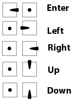
This functionality provides OSD joystick emulation for HS1177-style cameras, e.g. cameras having a single OSD input pin driven by a button resistor divider. Most cameras up to date seem to adhere to the design and have the following resistor nominals:
- 47 kΩ - camera internal resistor, 9.9 kΩ for RunCam Sparrow, Foxeer Monster and probably other HS1190 cameras (thanks to @khalinatek)
- 45 kΩ - enter
- 27 kΩ - left
- 15 kΩ - up
- 6.8 kΩ - right
- 0 - down
Setting up
resource camera_control PIN- allows you to designate aPINfor camera control functionality. The list of suitable pins depends on the way you're going to wire your camera to the FC.set camera_control_mode = hardware_pwm- mode of operation,software_pwmis the least restrictive in terms of available PIN selection, but it requires both a resistor and a capacitor to work properly;hardware_pwmis almost guaranteed to work with just a resistor given you can spare a timer for it;dac(not yet implemented) is going to be supported on the very few FCs that have a DAC pin broken out and unoccupied by other functions, and is going to work by direct connection to the camera once implemented.set camera_control_ref_voltage = 330- voltage (in 10 mV steps) measured across your camera's floatingOSDandGNDpins, usually 3V3, but not guaranteed, e.g. my RunCam Sky has 3V4, and some cameras have reportedly have as low as 3V1.set camera_control_key_delay = 180- the duration of each key press (in ms presence at thecamera_controlpin, after consulting with RunCam it was set to 180 ms to accommodate most cameras, while some of them accept as low as 125 ms.set camera_control_internal_resistance = 470- the internal resistance (in 100 Ω steps) of your camera, most HS1177 derivatives have 47 kΩ, but that's not guaranteed. You'll have to derive this value for your camera in case the default one doesn't work.camera_control_button_resistance = 450,270,150,68,0- sets the emulated resistance for each button on the equivalent button keypad for the camera. The default values should work for most cameras but in some cases the manufacturer may have unusual values. if you have problems (like one button won't work) then measure the actual resistance generated in the keypad that came with the camera and adjust. The button value ordering is:ENTER,LEFT,UP,RIGHT,DOWN. Added in Betaflight 4.1.
Modes of operation
Hardware PWM
Requires a 150-600 Ω resistor inline from your FC PIN to Camera OSD. This is built into some Additional GND connection is advised.
Assumes that the camera (or FC) has sufficient capacitance at OSD pin (look at Tips for hardware designers section). If you camera is not working, try adding a capacitor between camera OSD and GND.
How do I select a suitable PIN?
A pin with a hardware timer output is required to use the hardware PWM mode. Some FCs have a dedicated CC pin, which is preferable, as it usually already has the resistor in series, otherwise LED strip output or unused motor outputs (M5/M6) are a fairly safe bet. To check if a pin has a timer output, first find out what pin on the microcontroller the FC pin is wired to. This can be done using the resource command, example:
# resource
resource BEEPER 1 D02
resource MOTOR 1 B04
resource MOTOR 2 B00
resource MOTOR 3 B05
resource MOTOR 4 B01
resource MOTOR 5 D12
resource MOTOR 6 D13
resource MOTOR 7 C08
resource MOTOR 8 C09
...
resource SERIAL_RX 4 A01
In this case, if you for example wanted to use the unused M5 output on a quadcopter, the pin to use is D12. Check if the pin has a timer using the timer command:
# timer
timer A08 AF1
# pin A08: TIM1 CH1 (AF1)
timer B03 AF1
# pin B03: TIM2 CH2 (AF1)
timer B00 AF2
# pin B00: TIM3 CH3 (AF2)
timer B01 AF2
# pin B01: TIM3 CH4 (AF2)
timer B04 AF2
# pin B04: TIM3 CH1 (AF2)
timer B05 AF2
# pin B05: TIM3 CH2 (AF2)
timer D12 AF2
# pin D12: TIM4 CH1 (AF2)
timer D13 AF2
# pin D13: TIM4 CH2 (AF2)
timer C08 AF3
# pin C08: TIM8 CH3 (AF3)
timer C09 AF3
# pin C09: TIM8 CH4 (AF3)
We have a timer (TIM4) which is not used for anything else (the other pin, D13, is the M6 output, which we're not using).
Unmap the motor output pin, map the camera pin:
resource MOTOR 5 none
resource CAMERA_CONTROL 1 D12
And that's it, your pin should now be configured.
In case you want to use a pin that doesn't have a timer set up by default, you can check the available timers by using the timer command again. In this example, let's check if we can remap the rx pin from serial 4, which is on A01 in this example. As it wasn't listed in the list of configured timers, let's see if the pin can function as a timer output using timer a01 list:
# timer a01 list
# AF1: TIM2 CH2
# AF2: TIM5 CH2
In this case, TIM2 is already in use for pin B03, but TIM5 isn't in use anywhere. Enable the AF (alternate function) using timer A01 AF2, and you should be able to remap the pins.
timer A01 AF2
resource SERIAL_RX 4 none
resource CAMERA_CONTROL 1 A01
Software PWM
Requires a 150-600 Ω resistor and a 1-10 µF capacitor, forming an RC-filter. Resistor goes from PIN to OSD, while the capacitor should be connected between OSD and GND.

DAC
(Does not work, not implemented yet!)
Will require no additional components, wire your PIN to OSD, preferably with a GND connection as well.
Accessibility
- RC Stick Commands
MSP_CAMERA_CONTROL- MSP over Telemetry, e.g. Lua scripts for FrSky radios (Pull Request #23)
Stick Commands
Some cameras have a secondary OSD menu (for example the RunCam Eagle Pro 2) that allows setting things like voltage monitor, timers, display name, etc. This menu can be accessed as well, but you'll need to determine the appropriate stick commands based on the manual provided with the camera. The stick position will be equivalent to whatever button sequence the camera requires. So for example if the camera requires holding "down" button to enter the menu, this would correspond to holding the pitch stick "down" while entering camera control with the normal left stick throttle centered and yaw right. The point is that the roll/pitch stick corresponds to the up/down/left/right buttons and the throttle centered/yaw right corresponds to the "enter" button on the camera's control keypad or joystick.
Troubleshooting
First of all, make sure resource list CLI command lists camera_control as allocated.
If your camera doesn't work, chances are you have to adjust values for key delay, reference voltage or internal resistance. Defaults work fine for most HS1177-derivatives, if you have issues, try changing the key delay value first.
Key Delay
If you have multi-click occurrences, decrease the delay by 10-15%, if your clicks don't register consistently - try increasing it instead. Foxeer Arrow v3 is known to work best with delay of 125 ms.
Reference Voltage
Just measure the voltage between OSD and GND pins on the camera while it is powered.
Internal Resistance
Foxeer Monster, RunCam Micro Sparrow (and probably other cameras I haven't yet discovered) are known to require camera_control_internal_resistance = 99.
RunCam Phoenix 2 Nano requires camera_control_internal_resistance = 212.
To derive this value for an unknown camera, you'll need a multimeter and a suitable joystick. First set your multimeter to resistance measurement mode and measure the resistance of your OSD joystick while pressing individuals keys, write the values down somewhere, you'll need them later.
Now you'll have to power your camera, connect the OSD joystick to it and find a way to measure the OSD-pin voltage while pressing individual keys on joystick, measuring voltages for all keys is not necessary, one or two is sufficient. Also measure the Reference Voltage if you haven't yet.
You'll end up with a set of resistance and voltage values for each key. To find internal resistance value, plug in your values into this formula:
Rin = Rkey * (Vref / Vkey - 1) where key in (enter, left, up, right, down)
Calculate this value for a few keys as a sanity check, the resulting values should be roughly the same. The Rin you've arrived at is your camera_control_internal_resistance value, keep in mind it is measured in 100 Ω steps, hence divide your value by 100.
Keypad Button Resistance Values
Most cameras use standard resistance values for the keypad buttons, but some can have unusual values. If you have a problem with most of the buttons working but one or two not, try measuring and adjusting the camera_control_button_resistance values (added in Betaflight 4.1).
Example FC configurations
Emax Magnum stack + Foxeer Arrow v3
600 Ω resistor in line Camera control Mapped to Motor 6 output set camera_control_key_delay = 125
Use following CLI Commands
resource MOTOR 6 none
resource CAMERA_CONTROL A08
set camera_control_key_delay = 125
save
Foxeer Arrow Mini, Arrow Micro, Monster
These cameras have insufficient to no capacitance on OSD pin, as a result you'll have to add at least 0.1 µF to get Hardware PWM working. Foxeer may release a new revision which will address this problem.
1206 capacitors work perfectly while soldering directly to JST connector backside, here's an illustration of a 100 nF 1206 capacitor soldered onto an Arrow Micro v2, but it also works for Arrow Mini as they share PCB design:
![]()
A similar trick works for Foxeer Monster. @todo add a photo
Foxeer Predator
UP&DOWN do not work, hopefully future batches will have the firmware flaw addressed.
set camera_control_internal_resistance = 99
Predator expects a really low value for DOWN, while the FC can't output lower than 3.3 * R / (R + 9.9 kΩ).
Use a resistor of 75-150 Ω to make it work.
Reference voltage for my samples seems to be on the higher side, staying at 3.43 V for a 3S battery, which leads to the problem with UP. This camera seems to register UP key with a logic like:
if voltage is V_up:
  time_start = now
  while (voltage is not V_max): wait
  time_end = now
  total_time = time_end - time_start

  if total_time is short: UP
  else: LONG_UP
It results in the camera getting stuck in an infinite loop, even the OSD timer stops counting, as the FC can never output Vmax ~= 3.4.
Foxeer Predator v4 Mini measured internal resistance 47kΩ, reference voltage 3.27V, OSD joystick button resistances are standard (on the top of this article)
Caddx.us Micro Turbo S1
Works perfectly on the default settings, no capacitor required.
set camera_control_internal_resistance = 470
set camera_control_ref_voltage = 325
Caddx.us Micro Turbo F1
This camera has usually low reference voltage, at least no sample, running up a 4S battery it showed 2.77 V, works perfectly otherwise. No capacitor required.
set camera_control_internal_resistance = 470
set camera_control_ref_voltage = 277
Caddx.us Turtle V2
Based on the values measured with the procedure mentioned above. Found the button resistance values to be consistently above the default.
set camera_control_internal_resistance = 99
set camera_control_ref_voltage = 300
set camera_control_button_resistance = 460,280,160,78,10
Please follow manufacturers guidelines from the bottom of this page to avoid such problems!
Frequently asked questions
Which resistor value is best?
Any resistor from the 150-600 Ω will do, with preference to lower values.
Which resistor power rating is required?
Irrelevant
RCG Discussion Thread
Read this thread for help on compatibility.
Tips for hardware designers
If you're designing a flight controller, select an MCU pin which you'll be able to provide a dedicated timer for.
To add your camera control pin to default target resources assignment, use the following preprocessor macro in target.h file:
#define CAMERA_CONTROL_PIN pin_name
Use 150-220 Ω resistor inline between designated MCU pin and the solder pad. Consider adding some additional capacitance to support the widest variety of cameras, a 100 nF ceramic SMD capacitor would be sufficient, anything in the range of 100-500 nF will increase user experience greatly.
If you're designing a camera, the same advice about capacitance applies. It provides debouncing for the physical joystick and simplifies FC configuration for the end user. Having control over camera firmware, make it less restrictive in terms of key voltage levels with some 5-10% of margin from both sides.