BLUEJAYF4
Description
Beautifully simple STM32F4 based flightcontroller. An F4 replacement for the Naze.

Two variants (in multiple revisions). The full size, 36x36mm (30.5x30.5 mounting holes) and a 25x25mm (20x20 mounting holes) mini version.
MCU, Sensors and Features
Hardware
- MCU: STM32F405RTG6
- IMU: ICM-20602 (SPI) rev4, ICM-20608-G (SPI) rev3 (and mini), and MPU9250 (SPI) rev1 and rev2
- IMU Interrupt: Yes
- BARO: Optional on full size, not available on mini.
- VCP: Yes
- Hardware UARTS: 3 (4 on full size with Quad motor remapping)
- OSD: Compatible pinouts for MinimOSD on UART3 (stackable) on full size board
- Blackbox: Yes (16mb rev3, 2mb rev1), SD card for rev2 and rev3 full size (no SD card on mini)
- PPM/UART Shared: UART6
- Battery Voltage Sensor: Yes, directly connected, no wiring necessary (if using pololu on full size), wiring required to vbat supply on PDB if using mini
- Integrated Voltage Regulator: Pololu piggy back option on full size rev3 and rev4
- Button for putting board into DFU mode
Features
- Current Sensor: available as ADC input, but requires shunt circuit on PDB or battery cable.
- BlHeli passthrough: Yes
- WS2811 Led Strip: Yes (on motor output Pin 5)
- Transponder: No
Manufacturers and Distributors
These boards (full and mini) are available at some online RC stores, and directly from the manufacturer BlueJayRC.
Available here: BlueJayRC.com
Hardware Designs (if available)
The hardware is currently closed source. It may be in the future that older revisions will be made publicly available.
Variants
BlueJayF4 rev1, 2 and 3 - including mini.
Rev3 (mini) (there is also a PDB available)

Rev3 (Full Size)

Rev2 (Full Size)

Configuration Information
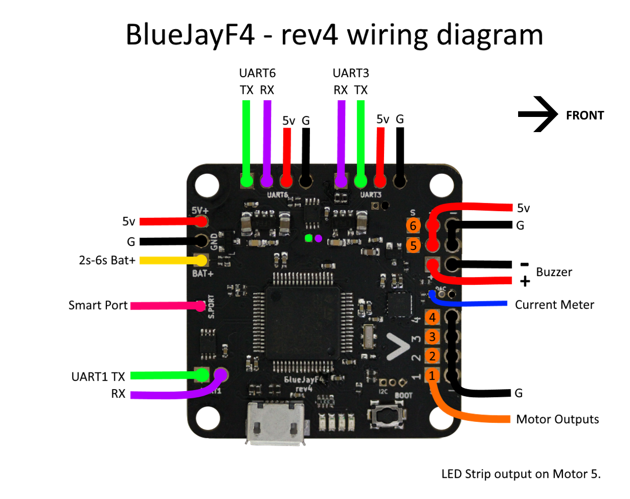
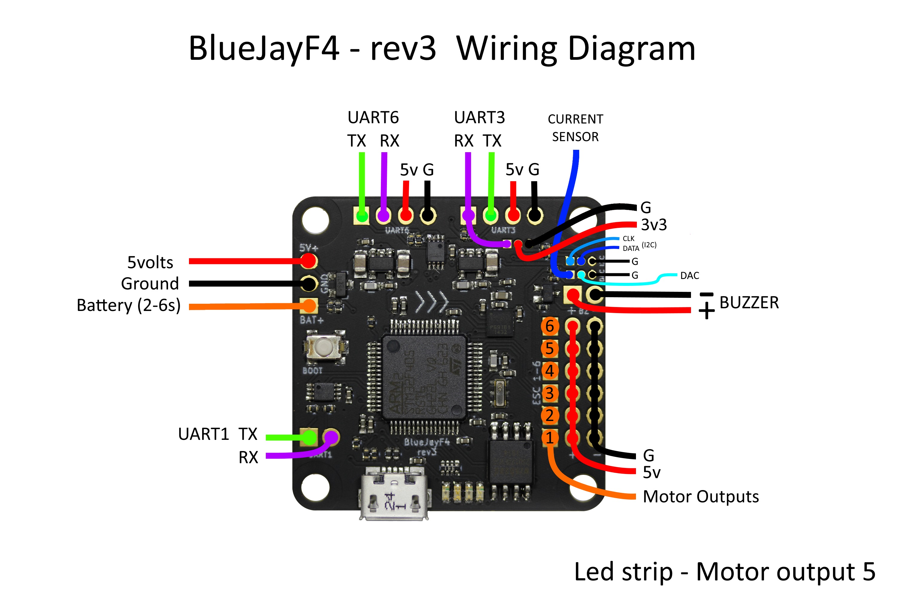
Wiring Diagrams
FrSky Smartport
Frysky smartport (or s-port) is inverted, and half duplex. You can modify your X4R or XSR by following the procedure here https://blck.mn/2016/06/smartport-the-frsky-x4rs-and-betaflight/ and here (for a cleaner modification thats easily switchable between inverted and non-inverted) https://blck.mn/2016/12/smartport-frsky-x4rs-and-betaflight-part-2/
For rev3 users, the addition of a diode on UART1, and the use of the builds in BF3.1 or later allow direct connection of s-port without modifying your RX unit.

You will need to run the following in the CLI:
set sport_halfduplex=OFF
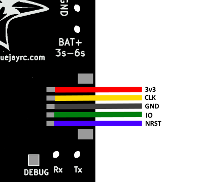
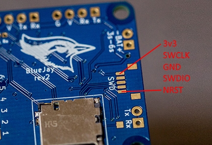
Serial Wire Debug
Serial Wire Debug output is located on the bottom of the board, and provides a pin out compatible with STM32Fx discovery boards to be used as a SWD adapter:
Known Issues:
The rev2 requires a resistor mod to prevent the issue of crashing on power up. The rev3 does not have this issue.
Following the picture below to perform the Rev2 resistor modification:

The rev2 onboard regulator is limited in current capacity, and has been replaced with a pololu piggy back option for greater flexibility.

Other Resources
Rcgroups Thread: http://www.rcgroups.com/forums/showthread.php?t=2593106
Configuring 4th UART (3.2 and later)
- 4th hardware UART (UART4) is supported on motor outputs 1 and 2, but it is hidden until explicitly turned on by resource commands.
- Motor outputs 1 and 2 must be remapped to avoid collision with UART4.
Example
Below is a sequence of resource commands to configure UART4, shift motor outputs by two (Motor 1 to motor output 3, motor 2 to motor output 4 and so on) and use DEBUG pad for LED strip.
# Disable functions on motor outputs 5 and 6 so motors can be shifted by two
resource SERIAL_TX 11 NONE
resource SERIAL_RX 11 NONE
resource MOTOR 5 NONE
resource MOTOR 6 NONE

# Remap LED
resource LED_STRIP 1 B03

# Remap motors
resource MOTOR 3 B00
resource MOTOR 4 B01
resource MOTOR 1 A02
resource MOTOR 2 A03

# Configure UART4
resource SERIAL_TX 4 A00
resource SERIAL_RX 4 A01