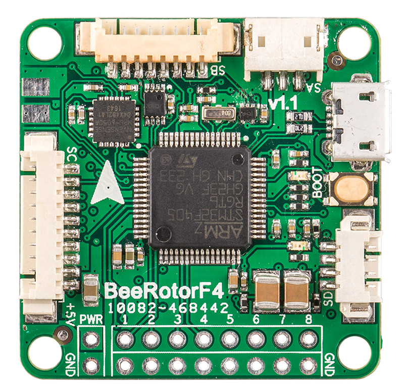
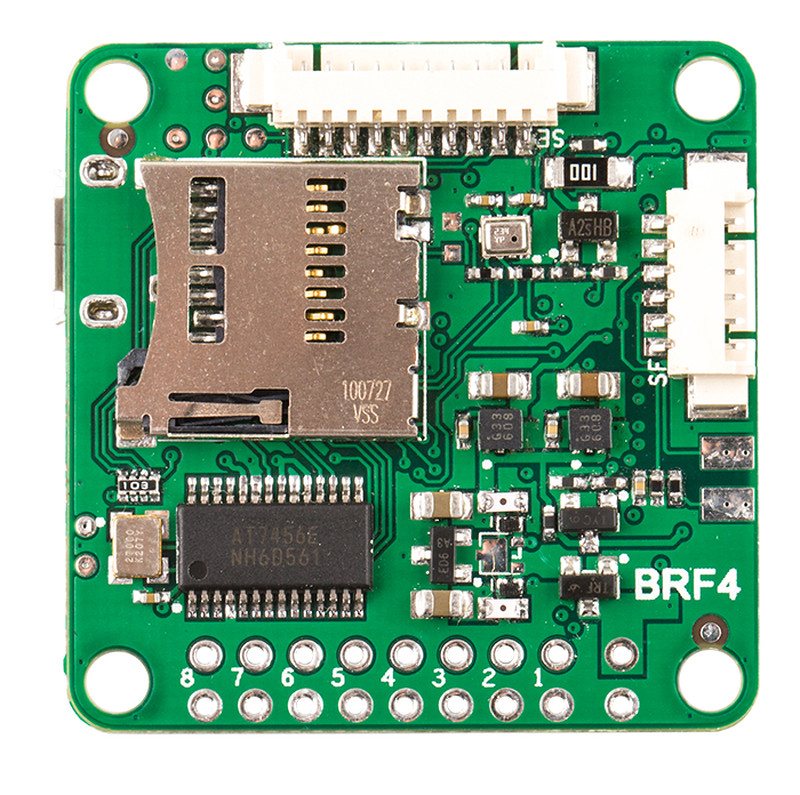
BeeRotor F4
Description
F4 board with integrated Betaflight OSD.
MCU, Sensors and Features
Hardware
- MCU: STM32F405
- IMU: MPU6050A (SPI)
- IMU Interrupt: yes
- BARO: BMP280 (I2C)
- VCP: yes
- Hardware UARTS: 1, 2, 3
- OSD: Betaflight OSD
- Blackbox: serial / SD Card
- PPM/UART Shared: UART2
- Battery Voltage Sensor: yes
- Integrated Voltage Regulator: no
- Brushed Motor Mosfets: no
- Buttons: BOOT
- 8 PWM / DShot outputs (up to 6 useable for DShot)
- LED strip output
- IR transmitter output
- switchable inverters for UART2 (SBus RX) and UART3 (SmartPort telemetry)
- SPI connector
Features
- 8 motor outputs (6 useable for DShot)
- integrated Betaflight OSD
- blackbox logging to SD Card
Manufacturers and Distributors
RCTimer: http://rctimer.com/product-1730.html
Designers
RCTimer: http://rctimer.com/
Maintainers
- Hardware: Eric Liang
- Software: Michael Keller
FAQ & Known Issues
- Enabling DShot for motor 6: Instructions
- The SI pin on the PDB connector does not have a voltage divider. If the PDB connector is used as input for the battery voltag measurement, the PDB has to have a voltage divider, or the MCU on the board will be immediately and permanently destroyed by the battery voltage! (The SI pad on the board does have a voltage divider. Use this if your PDB does not have a voltage divider.)