Power & Battery Tab
Set up all your power and battery related settings. Set the voltage and current sensor sources and calibration so that the FC can read the values and warn you accordingly. You can also check the current power measurements
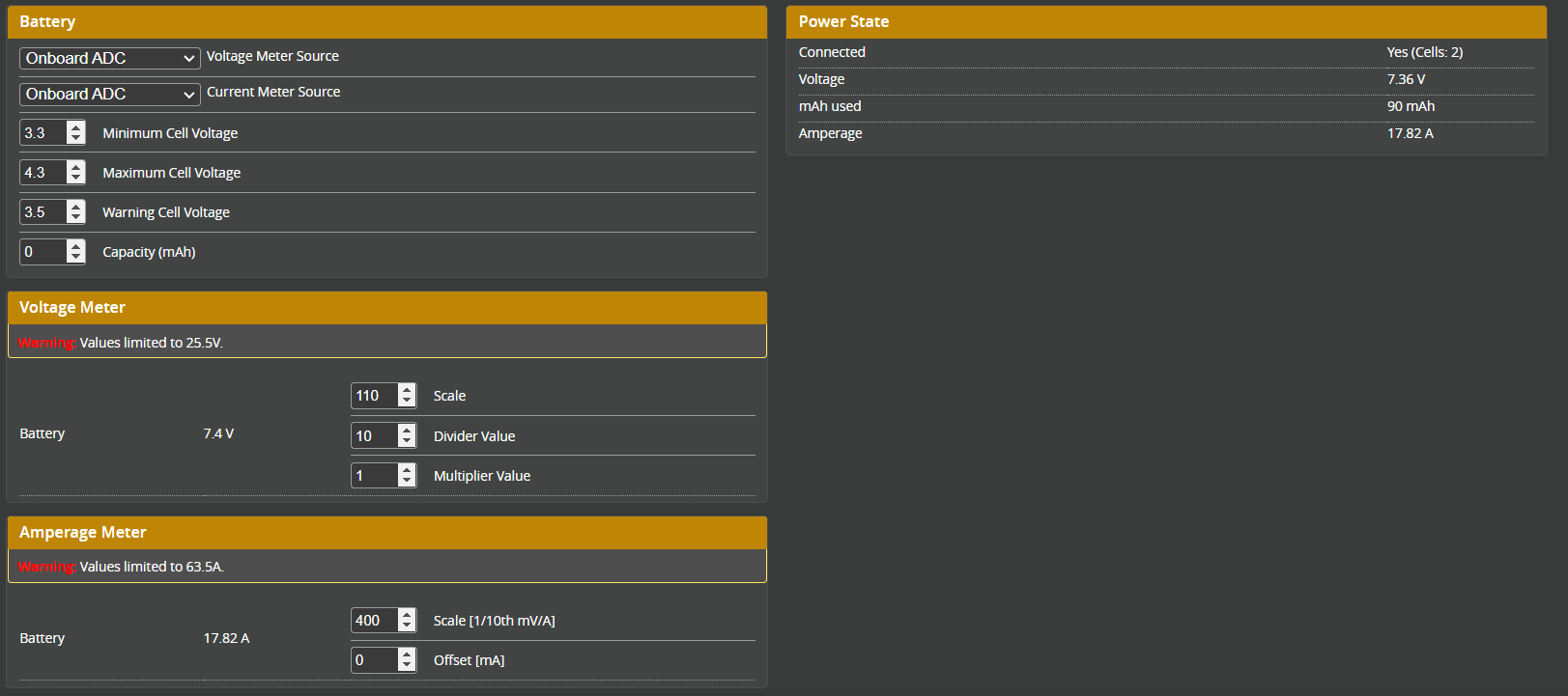
Battery
Voltage Meter Source
Select the source for the voltage measurements
- None - No voltage measurements will be available
- ESC Sensor - Use the ESC telemetry to get the voltage measurements
- Onboard ADC - Use the ADC on the flight controller to get the voltage measurements
Current Meter Source
Select the source for the current measurements
- None - No current measurements will be available
- ESC Sensor - Use the ESC telemetry to get the current measurements
- MSP Sensor/OSD Slave - NEEDS REVIEW, FOR ONCE I HAVE NO IDEA WHAT THIS MEANS
- Onboard ADC - Use the ADC on the flight controller to get the current measurements
Min/Max/Warning Cell Voltage
- Minimum Cell Voltage - The voltage that is considered critically low, and will trigger the corresponding warnings
- Maximum Cell Voltage - The voltage of a fully charged Cell
- Warning Cell Voltage - The voltage that is considered low, and will trigger the corresponding warnings
The warning voltage should be set to a value where you can still land safely, usually 3.6-3.5V.
The minimum voltage should be set to a value where damage is imminent, usually 3.3V.
If you fly a battery to less than 3.3V, it will start to be damaged and will not be able to hold a charge anymore, and can even be dangerous
Capacity
The capacity of the battery in mAh. This is used to calculate the remaining battery capacity in percent.
Voltage Meter
Settings for the voltage meter to measure the battery voltage correctly
Scale
The scale of the voltage meter. This is used to calculate the correct voltage from the ADC value. If the battery voltage is not displayed correctly, you can adjust this value up/down to fix it
Divider / Multiplier Value
This defines how the value read by the ICs ADC converts into a voltage value that makes sense to the pilot. In easy terms this sets how the ratio difference between the two voltage divider resistors are used in the voltage calculation formula.
Example:
Scale: 110 = 10:1 voltage divider (10k:1k ohm resistors)
Divider: 10 = sets the direct resistor to resistor ratio
Multiplier: 1 = this is to fine-tune the outcome of the calculation, a value of 1 is "no correction"
Amperage Meter
Settings for the amperage meter to measure the current draw correctly, using this formula:
Scale
The scale of the amperage meter. Used in the calculation to get the correct current draw from the ADC value
Offset
The offset of the amperage meter, rarely needed
Power State
- Connected - Yes/No, if Yes, also shows cell count
- Voltage - Voltage of the battery
- mAh Used - Capacity used in mAh
- Amperage - Current draw