PID Tuning Tab
Configure the PID controller settings, Filter settings, as well as the rates.
Betaflight has a profiles system that allows you to save multiple configurations for different scenarios. On the top left of the PID Tuning tab, it is possible to select the profile to be edited.
- Profile: 4 profiles that can be configured for PID & Filter settings.
- Rate Profile: 4 profiles that can be configured for Rate settings.
On the top right of the configurator, the following options are available:
- Copy profile: Make a duplicate of the current profile to another profile.
- Copy rateprofile: Make a duplicate of the current rate profile to another rate profile.
- Reset this Profile: Reset the current profile to default values.
- Show all PIDs: Show PID values for the Magnetometer.
- PID Profile Settings
- Rateprofile Settings
- Filter Settings
PID Profile Settings
Tune the PID controller settings for the craft. Detailed explanation can be found here.
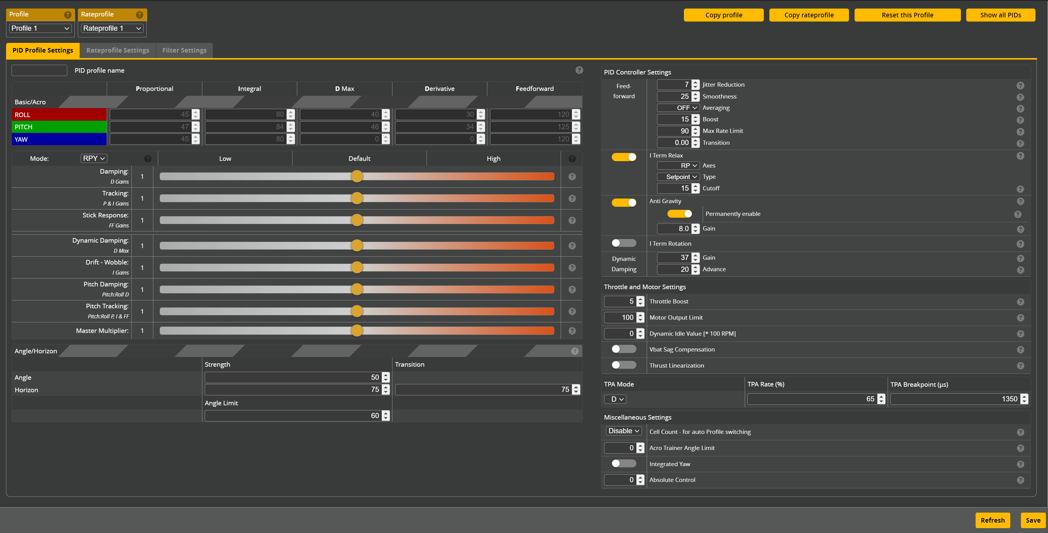
- PID profile name: PID profile name which can describe what conditions this profile was tuned to.
Betaflight allows to tune PIDs using simplified tuning. The sliders can be used to adjust the PID value indirectly.
When the Mode is set to OFF, the sliders are disabled, and the user can input the PID values directly.
Mode
- OFF: no sliders, enter values manually
- RP: sliders control Roll and Pitch only, enter Yaw values manually
- RPY: sliders control all PID values
Going from RP to RPY mode will overwrite Yaw settings with firmware settings.
Sliders
Sliders to adjust the aircraft flight characteristics (PID gains).
| Name | Description |
|---|---|
| Damping (D Gains) | Damping (D gain): Resists fast movement, minimises P oscillation. Relatively high D-gain will dampen stick responsiveness and may make motors hot, but should help control fast oscillations and will improve prop-wash. Relatively low D-term gives quicker stick responsiveness, but will weaken prop-wash performance and reacting to external forces (wind). |
| Tracking (P & I Gains) | Enhances the responsiveness of the aircraft, if too high may cause trilling or oscillation. Increase the Tracking slider to sharpen the aircraft's response to your commands and also outside influences; avoiding the nose of the aircraft going off course in any condition. Lower 'Tracking' values will have lots of bobbles and will go off course on stick moves and in prop wash. High 'Tracking' may result in oscillation and fast bounceback (hard to see, but you canhear). Excessive Tracking may result in oscillations and hot motors. |
| Stick Response (FF Gains) | Increases the responsiveness of the aircraft to faster stick movements. Lower Stick Response will increase the latency of the aircraft movements to commands and may result in slow bounceback at the end of a flip or roll. Higher Stick Response will give snappier aircraft response to sharp stick moves. Too much Stick Response can cause overshoots at the end of a flip or roll. Note: "I-term Relax" can reduce bounceback for low authority aircraft or if low Stick Response Gains are used. |
| Dynamic Damping (D Max) | Sets the maximum amount that D can be boosted to during fast movements. Increases D max, the maximum amount that D can increase to during faster movements. For race aircraft, where the main Damping slider has been set low to minimize motor heat, moving this slider to the right will improve overshoot control for quick direction changes. For HD or cinematic aircraft, instability in forward flight is best addressed by moving the Damping slider (not the Dynamic Damping slider) to the right. Check for motor heat and listen for weird noises during quick inputs when moving this slider to the right. For freestyle aircraft, especially heavier builds, moving this slider to the right may help control overshoot in flips and rolls. Note: Generally overshoot in flips and rolls is due to not enough 'i-Term Relax', or motor desyncs, or inadequate authority (a.k.a. Motor Saturation). If you find that moving the Damping Boost slider to the right doesn't improve flip or roll overshoot, put it back to the normal position, and seek out the reason for the overshoot or wobble. |
| Drift - Wobble (I Gains) | Fine adjustment of I. Increases or decreases I. Higher I may improve tracking in spiral turns, orbits, or 0% throttle commands. Too much I, particularly with not enough P, may cause wobbles or bounceback after flips/rolls or on chopping the throttle to 0%. Generally you want the 'Drift – Wobble' slider to be as high as it can be to keep the aircraft tracking in spiral turns, orbits, ect... but not so high that you start to see wobbles on chopping the throttle to 0%. Note: If you experience bounceback at any time that is easy to see, make sure that "I-term Relax" is enabled, and try lowering the iterm_relax_cutoff value. |
| Pitch Damping (Pitch:Roll D) | Increases the amount of damping on pitch relative to roll. Increases Damping (D) on the Pitch axis ONLY, i.e, for Pitch relative to Roll. Helps control Pitch specific overshooting or bounce-back. Aircraft with 'heavier' moment of inertia on the Pitch axis generally need more Damping authority (since Pitch has more inertia and accumulates more momentum). Tune the master 'Damping' and/or 'Tracking' sliders first, until you get good Roll axis behavior. Then use the Pitch sliders (increase or decrease) to fine tune the Pitch axis without affecting Roll. |
| Pitch Tracking (Pitch:Roll P, I & FF) | Increases stabilising strength on pitch relative to roll. Increases the Tracking strength on the Pitch axis ONLY, by changing Pitch P and I values relative to Roll. Allows stronger tracking authority on the Pitch axis relative to Roll. Increase to stabilise pitch (nose) bobble with sharp pitch inputs or throttle chops. Also consider raising Anti-Gravity gains. Tune the master 'Damping' and/or 'Tracking' sliders first, until you get good Roll axis behaviour. Then use the Pitch sliders (increase or decrease) to fine tune the Pitch axis without affecting Roll. |
| Master Multiplier | Increases all PID parameters equally. Don't change this slider unless you run out of adjustment on the other sliders. Typically this is only needed for low authority or high moment of inertia (MoI) aircraft like X-Class or cinelifter builds. Too much master gain may cause trilling oscillations or hot motors. |
PID Controller Settings
Feed-Forward
| Name | Description |
|---|---|
| Jitter Reduction | Reduces Feedforward when the sticks move slowly, regardless of their position. This allows smooth, jitter-free flight when making smooth slow arcs, yet provides full feedforward without any delay when the sticks are moved quickly. Transition is not required, and should be set to zero, when jitter reduction is active. |
| Smoothness | Feedforward smoothing is essential to attenuate noise in the feedforward trace. The smallest value that gives a smooth trace is best. |
| Averaging | Feedforward Averaging takes the average of the last 2 or 3 feedforward steps. This smooths the feedforward trace, but adds some delay. It is most effective when there is sequential up/down jitter in the signal, which is common with faster RC links. |
| Boost | Feedforward boost adds extra push in response to stick acceleration or deceleration. This minimises the gyro lag that is caused by motor acceleration delay, and reduces overshoot when the sticks decelerate by pulling back hard on the motors. |
| Max Rate Limit | Cuts feedforward as the sticks move towards maximum deflection, to minimise overshoot at the start of a flip or roll. Does nothing at the end of a flip or roll. Lower values make the attenuation start earlier. |
| Transition | Linearly reduces Feedforward when sticks are close to the centre. In 4.2 and earlier, transition can be used to provide smoother stick responses around centre stick position. In 4.3, transition is not recommended, as it has been 'replaced' by the jitter reduction function. A value of 0 disables transition. A value of 0.3 cuts feedforward to zero when sticks are at dead centre, but it increases to full normal when sticks are >30% out from centre. |
Others
| Name | Description |
|---|---|
| I Term Relax | Suppresses I Term accumulation when fast movements occur, reducing bounce-back at the end of rolls, flips and other quick inputs. Setpoint mode responds to smoothed stick inputs and works best for responsive aircraft. Gyro mode can be useful for extremely laggy aircraft. Usually iTerm Relax should not be applied to yaw. |
| Anti Gravity | Boosts I (and, in 4.3, P) during and shortly after fast throttle changes, increasing attitude stability during throttle pumps. Higher gain values may improve stability on low authority machines or those with an offset centre of gravity. |
| I Term Rotation | Rotates the current I Term vector properly to other axes as the aircraft rotates when yawing continuously during rolls and when performing funnels and other tricks. Very appreciated by LOS acro pilots. |
| Dynamic Damping - Gain | Increases the sensitivity of the system that increases D when the aircraft turns quickly or is shaking in propwash. Higher Gain values bring D up more readily than lower values, lifting D towards D Max more quickly. Values of 40 or even 50 may work well for clean Freestyle builds. Lower values will not raise D towards DMax except in really fast moves, and may suit race setups better by minimising D lag. WARNING: Either Gain, or Advance, must be set above about 20, or D will not increase as it should. Setting both to zero will lock D at the base value. |
| Dynamic Damping - Advance | Adds sensitivity to the Gain factor when the sticks are moved quickly. Advance does not respond to gyro or propwash. It acts earlier than the Gain factor and is occasionally useful for low authority aircraft that tend to lag badly at the start of a move. Generally it is best left at zero. WARNING: Either Advance, or Gain, must be set above about 20, or D will not increase as it should. Setting both to zero will lock D at the base value. |
Throttle and Motor Settings
| Name | Description |
|---|---|
| Throttle Boost | Transiently boosts throttle with faster throttle inputs, providing a more immediate throttle response. |
| Motor Output Limit | Percentage reduction in per-motor drive signal. Reduces ESC current and motor heat when using higher cell count batteries on high KV motors. When using a 6S battery on a aircraft that with 4S motors, props and tuning, try 66%; when using a 4S battery on a aircraft intended for 3S, try 75%. Be sure that all of your components can support the voltage of the battery you are using. |
| Dynamic Idle Value [* 100 RPM] | Improves control at low rpm and reduces risk of motor desyncs. It improves PID authority, zero throttle stability, inverted hang time, and motor braking. The Dynamic Idle min rpm should be set to around 3000 - 3500 rpm. Visit this wiki entry for more info. |
| Vbat Sag Compensation | Gives consistent throttle and PID performance over the usable battery voltage range by increasing motor output as battery voltage falls. The amount of compensation can be varied between 0 and 100%. Full compensation (100%) is recommended. Visit this wiki entry for more info. |
| Thrust Linearization | Improves low throttle authority and responsiveness. Especially useful for whoops and 48k ESCs. Has no effect at higher throttle. The amount of compensation can be varied between 0 and 150%. Usually 30-40% is enough. |
Miscellaneous Settings
| Name | Description |
|---|---|
| Cell Count - for auto profile switching | Set the number of cells in the battery to automatically switch profiles. |
| Acro Trainer Angle Limit | Helps pilots learn to fly in acro mode by limiting the angle that the aircraft can attain. Valid limits are 10-80 degrees. The mode must be activated with a switch in the Modes tab. |
| Integrated Yaw | Integrated Yaw integrates yaw P, I and D values, allowing yaw P, I and D to be tuned a bit like you'd tune pitch and roll. Very little I is required, because the integrated P acts like I, and integrated D acts like P. NOTE: Integrated Yaw requires use of Absolute Control, since no I is needed with Integrated Yaw. |
| Absolute Control | This feature solves some underlying problems of I Term Rotation and may replace it at some point. It accumulates the absolute gyro error in aircraft coordinates and mixes a proportional correction into setpoint. AirMode must be enabled and I Term Relax (for RP). When combined with Integrated Yaw, you can set I Term Relax enabled for RPY. |
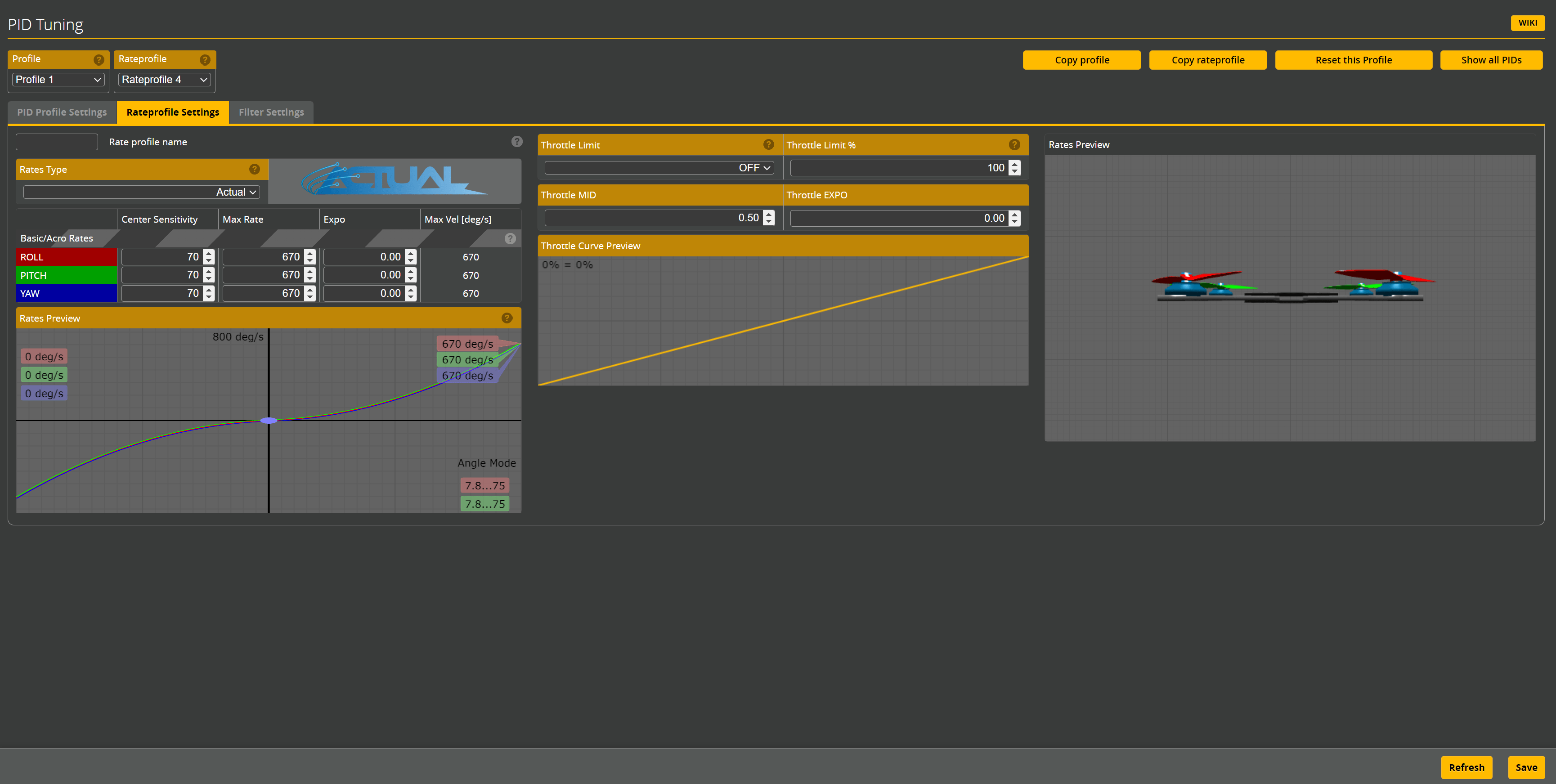
Rateprofile Settings
Adjust the rates for the aircraft.
-
Rate profile name: Rate profile name which can describe what type of flying this profile is for.
-
Rates Type: Changing rates type will change the rates curve and the way you can set it. Choose between:
- Actual (default)
- Betaflight (older betaflight rates)
- KISS
- QuickRates
- Raceflight
-
Rates and Expo: Determine your stick feel based on these parameters. Use the graph and live 3D model to find your favourite rate setting.
-
Rates Preview: Preview the rate curve in the graph. Play with the rates and see how those affect the stick curve.
| Name | Description |
|---|---|
| Throttle Limit | Select the type of throttle limiting. OFF disables the feature. SCALE will transform the throttle range from 0 to the selected percentage using the full stick travel. CLIP will set a max throttle percentage and stick travel above that will have no additional effect |
| Throttle Limit % | Set the percentage of throttle limit. |
| Throttle MID | Adjust the center of the expo curve. If Throttle Expo is 0, Throttle MID doesn't affect anything. |
| Throttle Expo | Add expo to the throttle curve |
- Rates Preview: 3D preview of the rates on the craft. Move the sticks to see how the rates affect the movement in real-time.
Filter Settings
Adjust the filter settings for the aircraft.
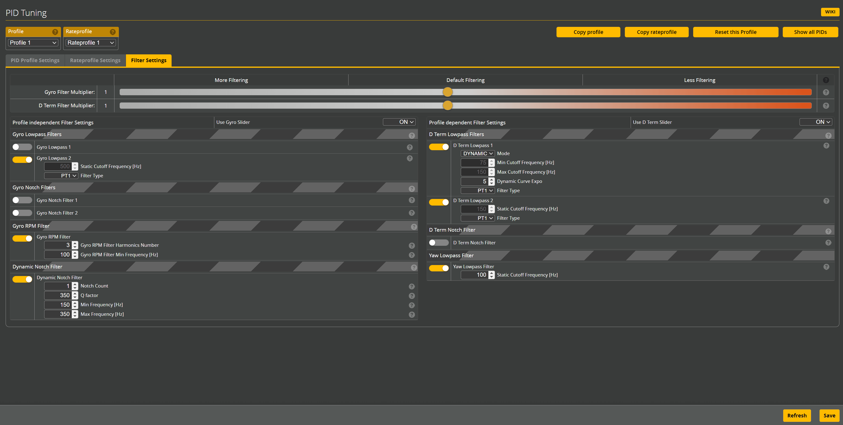
Sliders
These sliders adjust the Gyro and D-term filters.
| Name | Description |
|---|---|
| Gyro Filter Multiplier | Changes the Gyro Lowpass filter cutoffs. Moving the slider to the left gives stronger Gyro filtering (lower cutoff frequency). Moving the slider to the right gives less Gyro filtering (higher cutoff frequency). When moving the slider to the right to improve propwash handling, BE CAREFUL to not get too radical. You will allow more noise into both P and D and may get flyaways or burnt out motors. You may need to move the slider to left if you have frame resonance issues, bad bearings, beat up props, hot motors, etc. Gyro filtering is applied before, and in addition to, D filtering. |
| D Term Filter Multiplier | Changes the D-term Lowpass Filter cutoffs. Moving the slider to the left gives stronger D filtering (lower cutoff frequency). Moving the slider to the right gives less filtering (higher cutoff frequency). D-term is the most sensitive PID element to noise and resonance. It can amplify high frequency noise by 10x to 100x. That's why D filter cutoffs are much lower than the gyro filters. D-term filtering is applied after, and in addition to, the gyro filtering. The default D filtering is optimal for most aircraft and rarely needs changing. Moving this slider to the left reduces motor heat in noisy aircraft and with high PID 'D' tunes, but we may see more propwash and lower frequency D resonances. Moving the slider to the right is not recommended, but may improve propwash on clean builds. It may cause motor grinding on arming, sudden resonances in-flight, and serious motor overheating. |
Profile Independent Filter Settings
These settings are independent of the profile and are applied to all profiles.
Use Gyro Slider: Whether to use the Gyro Filter Multiplier. If disabled, the values have to set manually.
Gyro Lowpass Filters
| Name | Description |
|---|---|
| Gyro Lowpass 1 | The use of gyro lowpass 1 in dynamic mode was important with the earlier dynamic notch code. Gyro lowpass 1 can usually be disabled completely in firmware 4.3 when RPM filtering is used, unless the gyro has no internal hardware filtering. In dynamic mode, filtering will be stronger at low throttle, with less filtering and less delay as throttle increases. The transition from low to high cutoff will happen earlier, as throttle increases, with higher Gyro lowpass expo values. In static mode, the cutoff frequency is fixed. Filter type defaults to PT1. Higher order filtering is rarely required. |
| Gyro Lowpass 2 | This filter runs in the gyro loop, filtering the signal before it enters the PID loop. It is always in static (fixed cutoff) mode. If the PID loop frequency is less than the gyro loop frequency, eg a 4k PID loop with an 8k gyro loop, this filter should be retained to prevent aliasing issues due to 8k->4k downsampling. A single gyro lowpass 2 configuration, set to somewhere 500 and 1000Hz, works well for Betaflight 4.3 or higher, for clean builds with RPM filtering active and at least default D filtering. |
Gyro Notch Filters
| Name | Description |
|---|---|
| Gyro Notch Filter 1 | Applies a static (constant frequency) notch filter to Gyro, at the specified Center frequency. May be useful for isolated, constant frequency resonances that affect both P and D. To be useful, the resonant frequency must be constant across the throttle range. Notch width is set by the cutoff frequency. Cutoff should typically be set between 10% and 40% below centre frequency. Use the tightest filter range that controls the resonance. Avoid setting notch filters below 100hz except in special circumstances. |
| Gyro Notch Filter 2 | Applies a second static (constant frequency) notch filter to Gyro. This is rarely required, and should only be used as a last resort to combat a second fixed frequency resonance line that can't be controlled by other means. |
Gyro RPM Filter
RPM filtering is a bank of notch filters on gyro which use the RPM telemetry data to remove motor noise with surgical precision.
The ESC must support the Bidirectional DShot protocol and the value of the Motor poles in the Motors tab must be correct for this filter to work.
| Name | Description |
|---|---|
| Gyro RPM Filter Harmonics Number | Number of harmonics per motor. A value of 3 (recommended for most aircraft) will generate 3 notch filters, per motor for each axis, totaling 36 notches. One at the base motor frequency and two harmonics at multiples of that base frequency. |
| Gyro RPM Filter Min Frequency [Hz] | Minimum frequency that will be used by the RPM Filter. |
Dynamic Notch Filter
The Dynamic Notch Filter tracks peak motors noise frequency peaks and places notch filters at those frequencies, independently for each axis.
| Name | Description |
|---|---|
| Notch Count | Sets the number of dynamic notches per axis. With RPM filter enabled a value of 1 or 2 is recommended. Without RPM filter a value of 4 or 5 is recommended. Lower numbers will reduce filter delay, however it may increase motor temperature. |
| Q Factor | Adjust how narrow or wide the dynamic notch filters are. Higher value makes it narrower and more precise and lower value makes it wider and broader. Having a really low value will greatly increase filter delay. |
| Min Frequency [Hz] | Set this to the lowest incoming noise frequency that is needed to be controlled by the dynamic notch. |
| Max Frequency [Hz] | Set this to the highest incoming noise frequency that is needed to be controlled by the dynamic notch. |
Profile Dependent Filter Settings
These settings are dependent on the profile and are applied to the selected profile.
Use D Term Slider: Whether to use the D Term Filter Multiplier. If disabled, the values have to set manually.
D Term Lowpass Filters
| Name | Description |
|---|---|
| D Term Lowpass 1 | In dynamic mode, filtering will be stronger at low throttle, with less filtering and less delay as throttle increases. This helps control motor grinding or unexpected flyaways on arming, while reducing delay and propwash after takeoff. The transition from low to high cutoff will happen earlier, as throttle is increased, with higher D-term lowpass expo values. In static mode, the cutoff frequency is fixed. This is not recommended for D filtering. Filter type defaults to PT1, though some users have used only a single dynamic Biquad filter here, with no second PT1. Changes that result in less D filtering may cause serious motor overheating or flyaways on arming. |
| D Term Lowpass 2 | This filter is always in static (fixed cutoff) mode. At least two PT1 lowpass filters, or a single second order filter, are required for D filtering. Usually this cutoff is set to the higher value of the dynamic lowpass 1 range. This provides second order noise control above that frequency. Changes that result in less D filtering may cause serious motor overheating or flyaways on arming. |
D Term Notch Filter
Applies a static (constant frequency) notch filter to D-Term data, at the specified Center frequency. Notch width is set by the cutoff frequency. May be useful for isolated, constant frequency resonances that are amplified by D. Keep the cutoff as close to centre as possible. Avoid setting notch filters below 100hz except on low RPM builds.
Yaw Lowpass Filter
Applies a PT1 filter at the specified cutoff frequency to Gyro data on the yaw axis.