Hardware
There's a lot of parts that go into making FCs function the way they do, with different sensors, power management and outputs. This page will go over the different parts of a FC, what they do, and which parts are being used.
Main Components & General IO
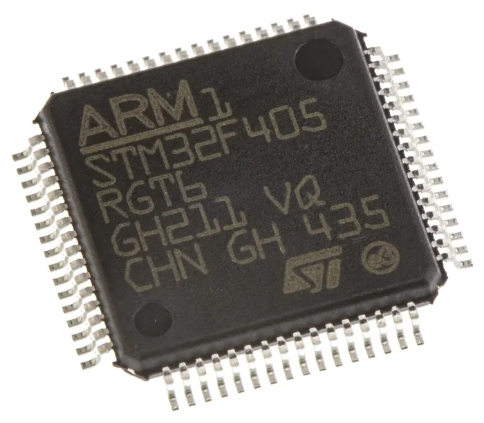
MCU
MCU (Microcontroller Unit) is the main chip on the FC, you can think of it as the "brain". It's responsible for running the flight controller software, and processing all the data from the sensors. From those inputs it does a bunch of magic computation to generate the signals that go to the ESCs and run the motors.
Most FCs use MCUs that are based on the ARM Cortex architecture. Most often made by STM, but recently there's been a few MCUs from ArteryTek used.
You have most likely seen something like "F4", "F7", or maybe further specified as "F411", "F405", and "F722". These are designations for the different MCU lines. They vary in flash size, RAM, and clock speed. Generally, the higher the number, the more powerful the MCU is.
In order of power, from least to most:
- STM32F411 - Very common in budget and/or AIO FCs due to its low cost and small size. But it's not that powerful compared to most other MCUs
- STM32G473 - A newer option from STM, it's a bit more powerful than the F411, but not as developed and established
- STM32F405 - Pretty much the most common option, it's a good balance of power and cost, being in use for a long time
- AT32F435 - ArteryTek's new alternative to the F405, directly pin-compatible, but with a bit more power
- STM32F722 - Very popular high-end option, but it has a limited flash size. This is not much of a problem nowadays with the Cloud Build system which allows a lot of space saving
- STM32F745 - Somewhat more powerful than the F722, but with more available flash space make it a good option for high-end builds without going overboard
- STM32H743 - The most powerful (and expensive) option. It's not really needed for most builds, but it's a good option if you want to go all out
Voltage Regulator
The voltage regulator is responsible for taking the input voltage and stepping it up/down to the voltage that the MCU and other components need. The MCU and onboard sensors usually run at 3.3V, and external peripherals like receivers, cameras, and some lower-power VTXs run at 5V. For running higher power VTXs, or basically most of the Digital options out there, you may see a 9/10/12V regulator (though 12V is recommended nowadays).
If one or more of the regulators are overloaded, they may cause the rest of the electronics to not function properly, not function at all, or even destroy the regulation circuitry (in some cases the components connected to it as well). This is why it's important to make sure that the regulator is rated for the current draw of the components you're using. On most hardware configurations this should not be an issue, but for example when running a lot of LEDs, it is possible to overload the 5V regulator.
OSD
To get OSD on analog video, the FC takes in the raw video signal directly from the camera, and feeds it through the MAX7456 chip (also the AT7456E - a drop-in replacement) which is used to overlay basic sprites defined in the font file on top of the video. The modified analog video is then sent out to the VTX to be transmitted.
For Digital video systems, an analog OSD chip is not necessary, as the OSD information is transmitted to the digital VTX to be sent out along with the video, and only gets overlaid in the goggles. This allows clean video recording, and export of the OSD data among other things.
Positioning Sensors
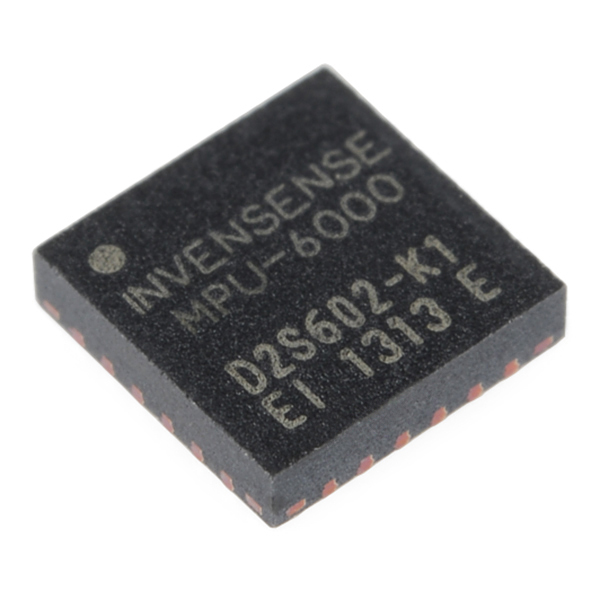
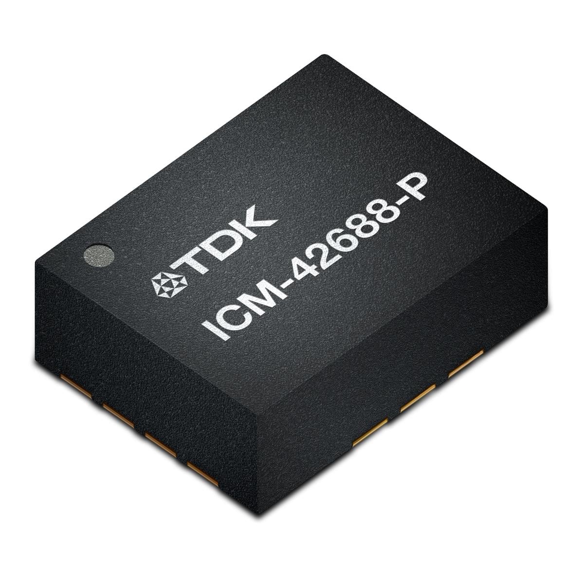
Gyroscope/Accelerometer
Uses gyroscopic principles to measure the orientation and angular velocity of the FC. The gyroscope measures the angular velocity, and the accelerometer measures the orientation.
- The gyro is used for flight modes that do not require the FC to know how it's oriented, only needing the velocity, such as Acro mode
- An accelerometer is used to measure the orientation of the FC in flight modes/features that require spatial orientation, such as Angle/Horizon mode, and GPS Rescue
Pretty much every FC has a single chip package that contains both the gyro and accelerometer, usually communicating over SPI. Similar to the MCU's, there is a lot of variety:
-
Invensense MPU6000 - It has been in use for a very long time, and is still regarded by many as the best option. It went out of production at one point (which pretty much kickstarted all of the other options), but it's back now
-
Bosch BMI270 - One of the best alternatives to the MPU6000. However to make it perform the best, it runs at a lower speed than most of the rest (8KHz on the MPU6000, 3.2KHz on the BMI270)
-
Invensense ICM42xxx/ICM20xxx - A newer option, spread in use when the MPU6000 went out of production for a little while. It used to perform worse, but past version 4.4.1, it's on par (or even better) than the MPU6000. No need to worry about products using them
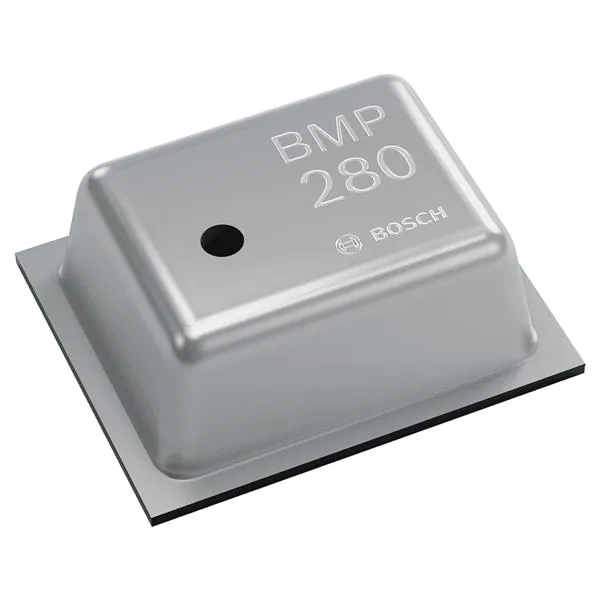
Barometer
Used to measure the air pressure, which can be used to calculate the altitude of the sensor. It's used in GPS Rescue modes to safely lnd and more. In the future planned for altitude hold and even more advanced features.
The most often-used barometer you'll see on most FCs is the Bosch BMP280. There are some others like the BMP180, MS5611 or DPS310, but they're not as common.
The barometer chips need to have a hole in the package itself (see pictures below), so that it can even get a reading of the air pressure. You put use a piece of open-cell foam on top to help get a better measurement. If you are using conformal coating, make sure to not cover the hole, or the barometer will not work.
Magnetometer
Measures the magnetic field around itself - basically just a compass. Used to tell the orientation of the FC relative to the Earth's magnetic field. In the current 4.4.1 release, it's not yet fully worked out to aid the advanced GPS Rescue, but it's planned for releases to come.
Magnetometers (as the name would suggest) are very sensitive to magnetic fields. This includes electronic interference, be that from the motors, ESCs, or the VTX/receiver. It's recommended to keep the magnetometer as far away from these as possible if you're using an external one (GPS units often come with them integrated), and to calibrate it carefully to get usable results.
GPS
Used to get the position of the FC, and the speed it's moving at, utilizing the Global Positioning System which is a network of satellites orbiting the Earth. Can also be used with more local systems like GLONASS, and Galileo. This gives the FC accurate position and speed data, which can be displayed on the OSD, sent back to the radio for localization after a crash, or even bring the craft back to you with GPS Rescue.
Most GPS units on the market are based on the M8 chipset from uBlox. However, there are newer modules that use the M10 chipset. These work much better than M8... with a slight catch. Prior to the 4.5.0 release, the M10 was not supported for auto-configuration in Betaflight, As such, it required manual configuration in the u-center software. When not properly configured, it results in unreliable performance. From release 4.5.0, manual configuration is no longer necessary.