Gear Up AirBrain H743
- Specifications
- Wiring Diagrams
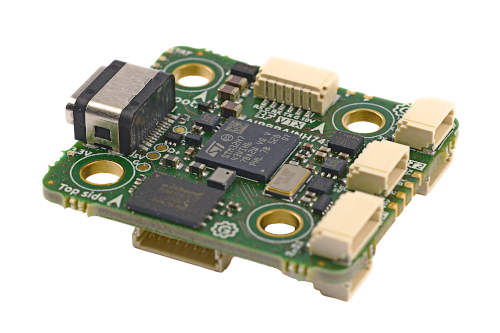
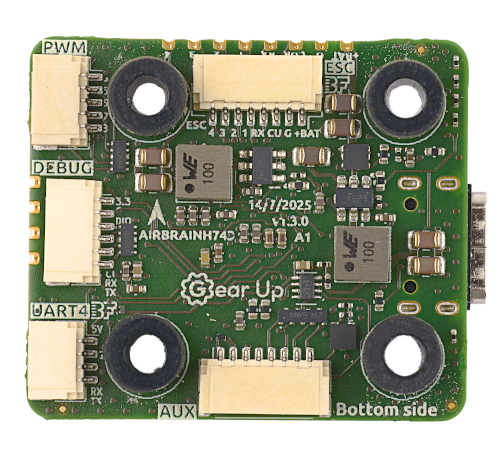
- Photos
- Datasheet
- Buy

Other Features
- 3-10s LiPo support
- Magnetometer (Compass): LIS2MDL
- Hardware Inverter: Yes
- Onboard RGB LED: Betaflight controlled LEDs, 1x Red, 1x Green, 1x Blue
- 2 x Power LED
- Built in voltage monitoring
- Made in Europe 🇪🇺
- SD Card Slot: No
- Onboard Receiver: No
- Bluetooth: No
- WiFi: No
Information
Gear Up AirBrain H743 is made in Europe and NDAA compliant
Input/Output
- USB Connector: USB Type-C
- Motor Outputs: 8x
- UARTs: 7
- I2C: Yes
- SWD: Yes
- SPI: Yes
- 3.3V Output: Yes, MAX 0.5A
- 5V (VBUS) Output: Yes, when powered from USB, only UART2 connector gets 5V
- 5V Output: Yes, MAX 2A
- 10V Output: Yes, MAX 2.5A
- Current Sensor: Yes
- Analog RSSI Input: No
- LED Strip Output: Yes
- Buzzer Output: Yes
Connectors
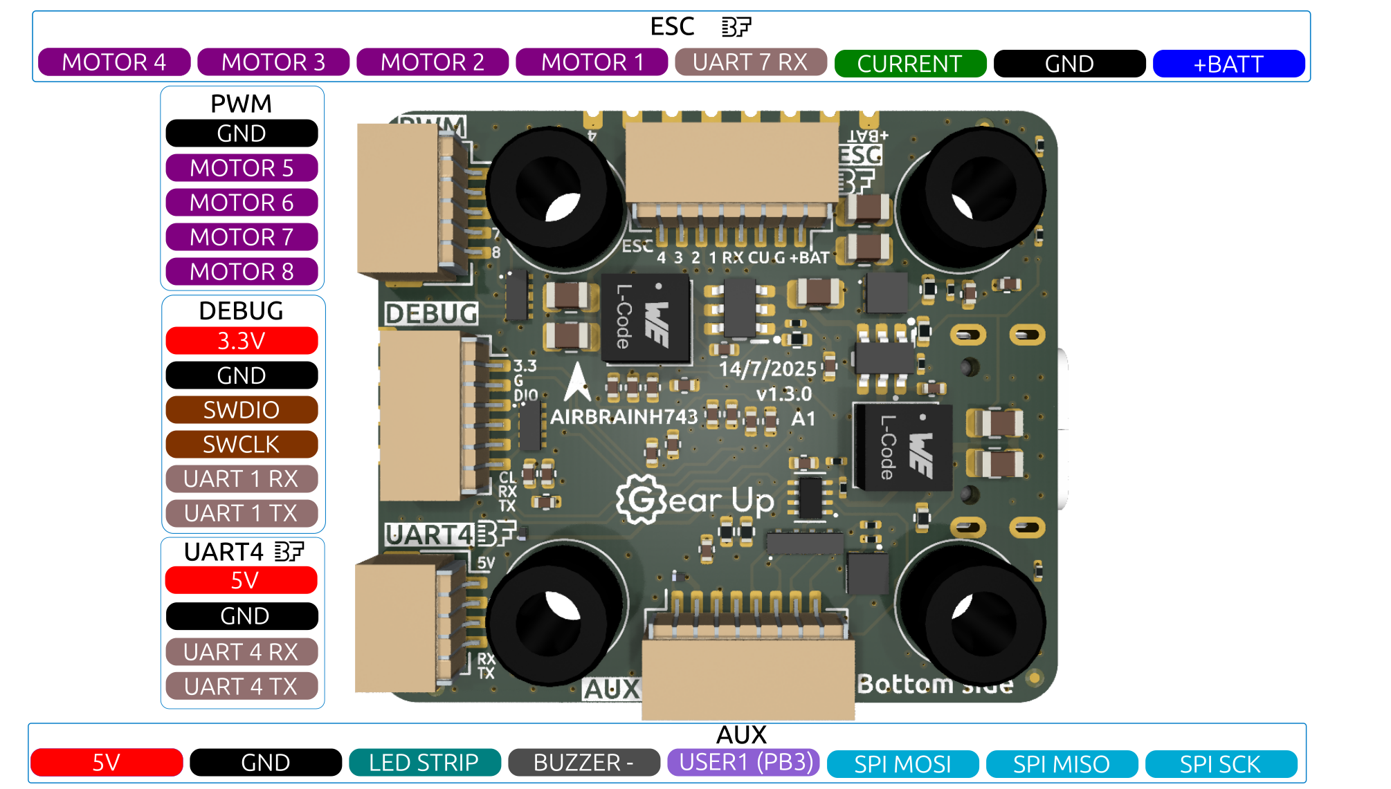
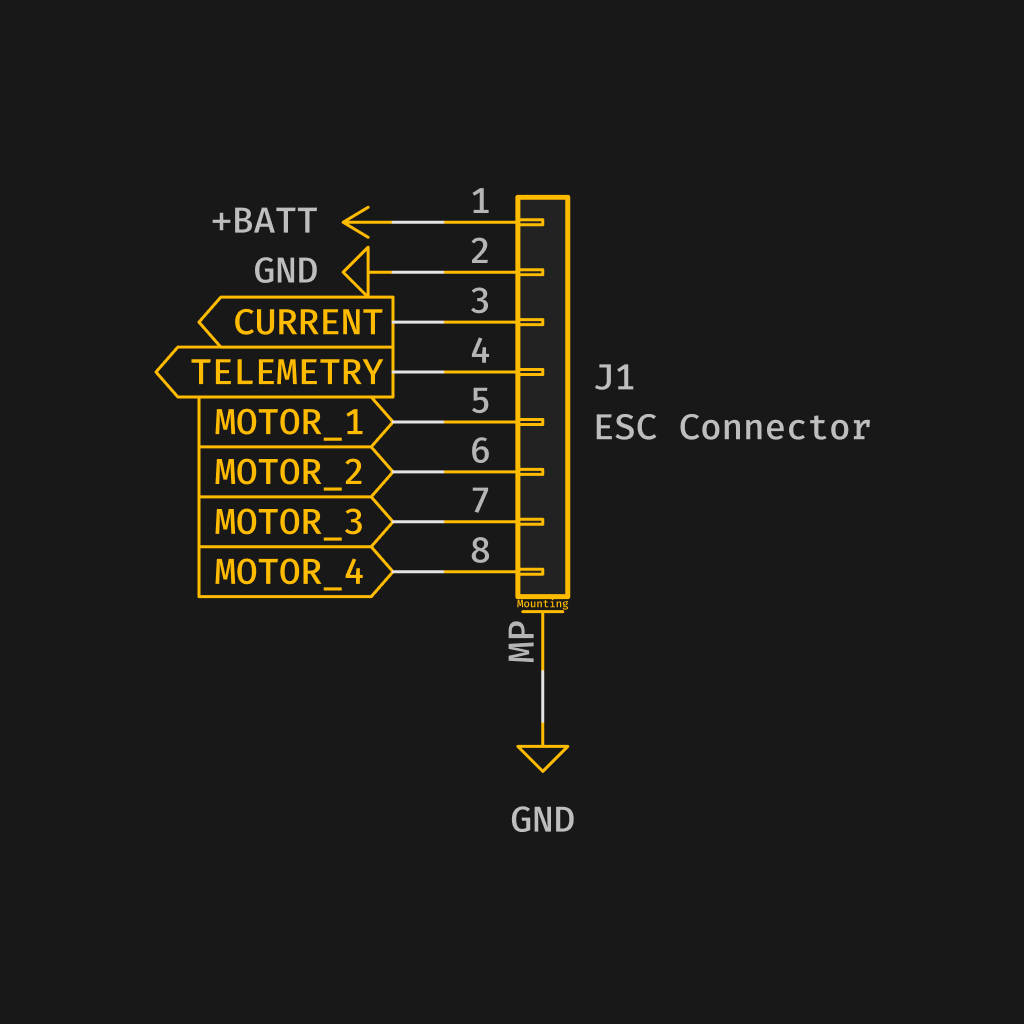
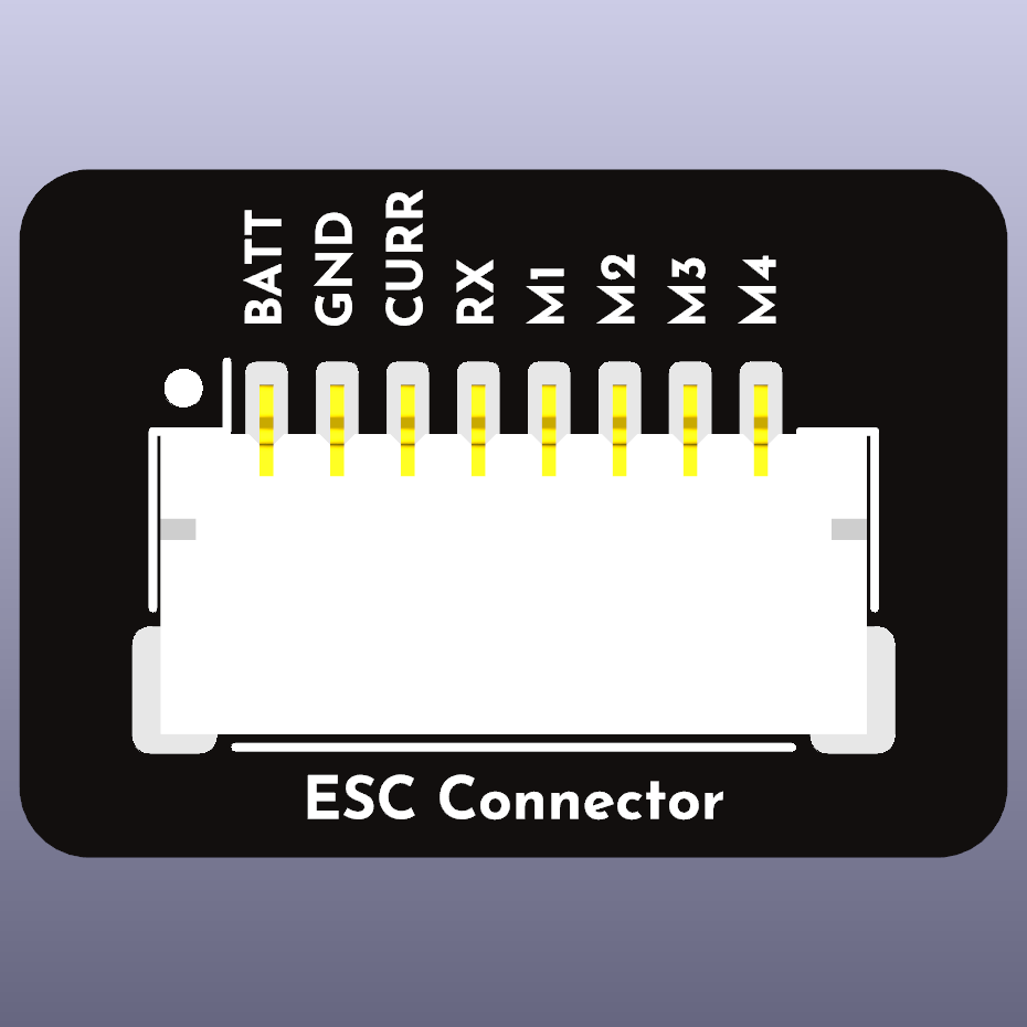
ESC (Motor 1-4)
The pin configuration for the JST SH connector is as follows:
| Pin # | Name | Label | Notes |
|---|---|---|---|
| 1 | V+ (VBAT) | +BAT | Power input (10-42V) |
| 2 | GND | G | Ground |
| 3 | Current | CU | Current (PC5) |
| 4 | UART 7 (Telemetry) | RX | UART 7 RX |
| 5 | Signal 1 | 1 | Motor 1 |
| 6 | Signal 2 | 2 | Motor 2 |
| 7 | Signal 3 | 3 | Motor 3 |
| 8 | Signal 4 | 4 | Motor 4 |
UARTs
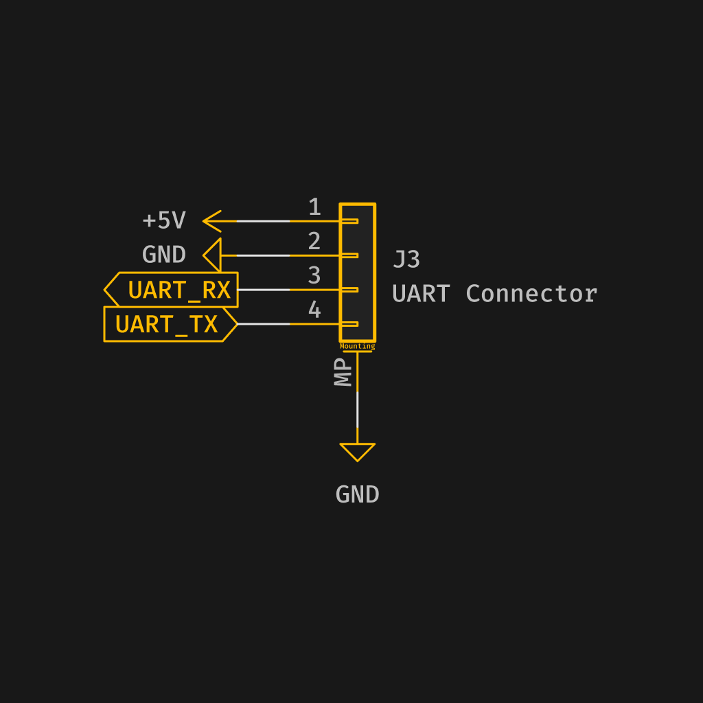
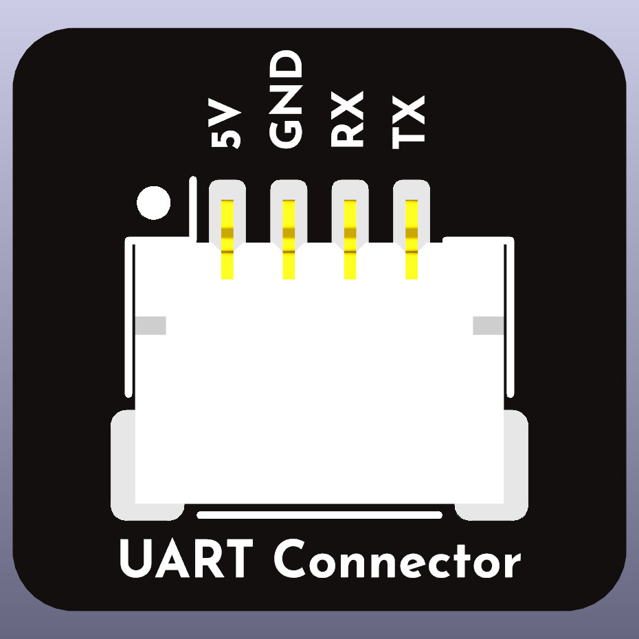
UART 2
The pin configuration for the 4-pin JST SH connector is as follows:
| Pin # | Name | Label | Notes |
|---|---|---|---|
| 1 | V+ (5V) | 5V | Power output |
| 2 | GND | G | Ground |
| 3 | UART 2 RX | RX | UART 2 RX |
| 4 | UART 2 TX | TX | UART 2 TX |
The '5V' from UART2 connector is also powered when connected via USB. All other 5V outputs only work when powered through battery.
UART 4
The pin configuration for the 4-pin JST SH connector is as follows:
| Pin # | Name | Label | Notes |
|---|---|---|---|
| 1 | V+ (5V) | 5V | Power output |
| 2 | GND | G | Ground |
| 3 | UART 4 RX | RX | UART 4 RX |
| 4 | UART 4 TX | TX | UART 4 TX |
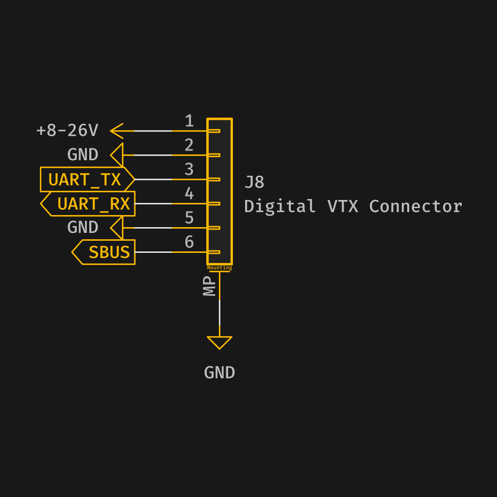
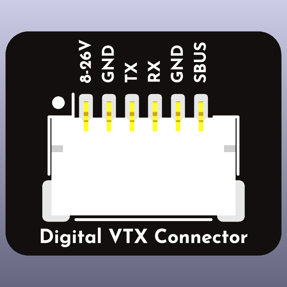
Video Transmitter
The current pin configuration for the JST SH connector is as follows:
| Pin # | Name | Label | Notes |
|---|---|---|---|
| 1 | V+ (10V) | 10V | Power output |
| 2 | GND | G | Ground |
| 3 | UART 3 TX | TX | UART 3 TX |
| 4 | UART 3 RX | RX | UART 3 RX |
| 5 | GND | G | Ground |
| 6 | UART 5 RX | RX | UART 5 RX |
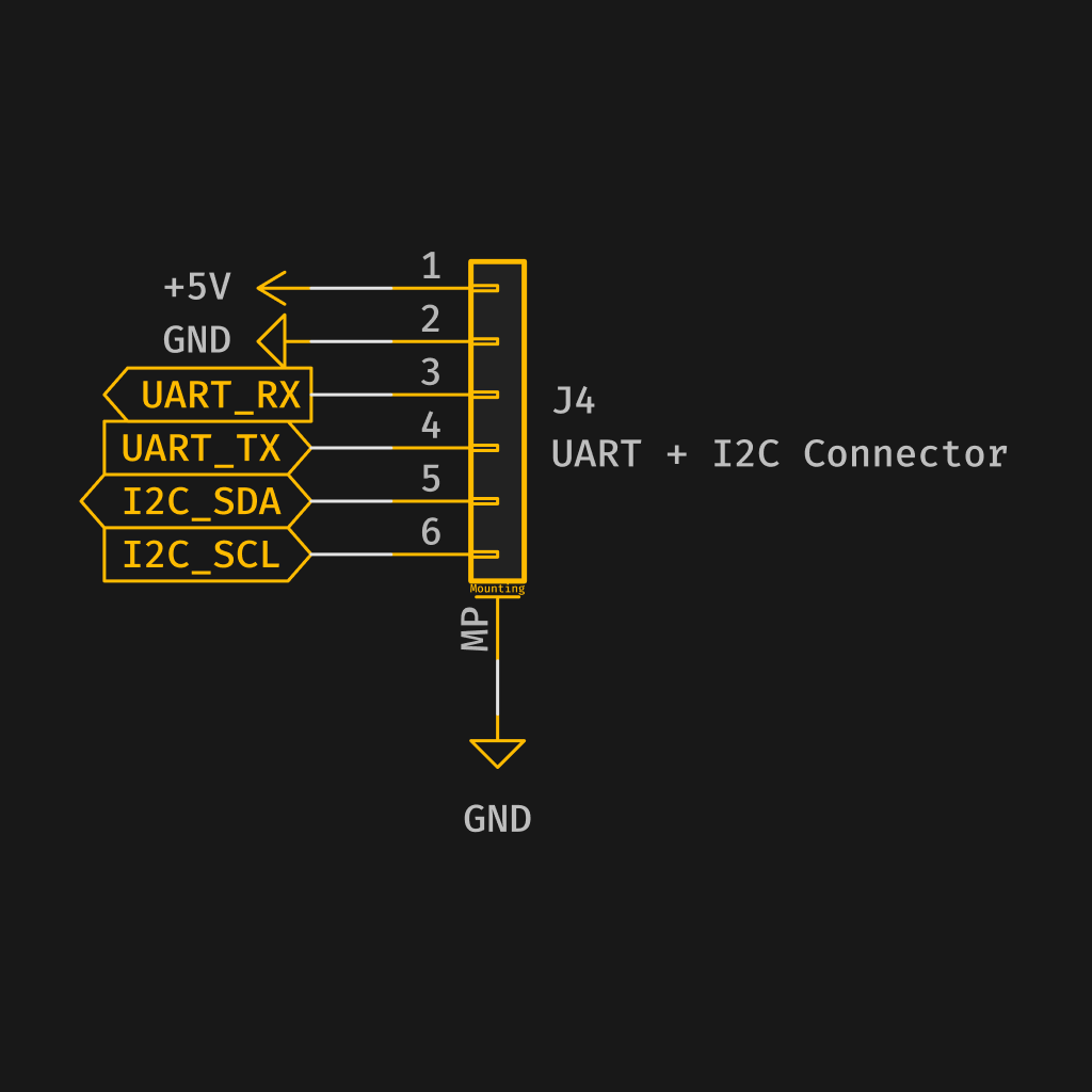
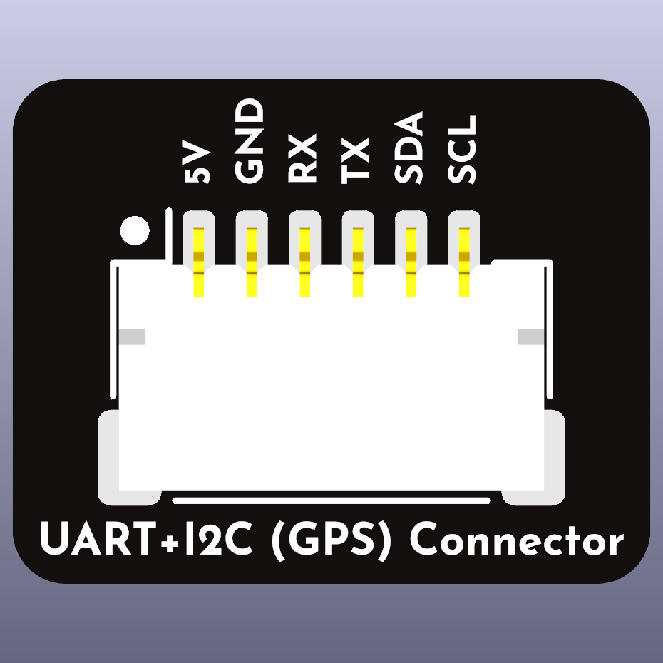
GPS
The pin configuration for the 6-pin JST SH connector is as follows:
| Pin # | Name | Label | Notes |
|---|---|---|---|
| 1 | V+ (5V) | 5V | Power output |
| 2 | GND | G | Ground |
| 3 | UART 8 RX | RX | UART 8 RX |
| 4 | UART 8 TX | TX | UART 8 TX |
| 5 | I2C SDA | SDA | I2C SDA |
| 6 | I2C SCL | SCL | I2C SCL |
Motor 5 - 8
The current pin configuration for the JST SH connector is as follows:
| Pin # | Name | Label | Notes |
|---|---|---|---|
| 1 | GND | G | Ground |
| 2 | Signal 5 | 5 | Motor 5 |
| 3 | Signal 6 | 6 | Motor 6 |
| 4 | Signal 7 | 7 | Motor 7 |
| 5 | Signal 8 | 8 | Motor 8 |
Auxiliary
The current pin configuration for the JST SH connector is as follows:
| Pin # | Name | Label | Notes |
|---|---|---|---|
| 1 | V+ (5V) | 5V | Power output |
| 2 | GND | G | Ground |
| 3 | LED STRIP | LED STRIP | |
| 4 | BUZZER - | BUZZER - (Buzzer minus) | |
| 5 | USER1 | USER1 (PB3) | |
| 6 | SPI MOSI | SPI MOSI (PE6) | |
| 7 | SPI MISO | SPI MISO (PE5) | |
| 8 | SPI SCK | SPI SCK (PE12) |
Debug
The current pin configuration for the JST SH connector is as follows:
| Pin # | Name | Label | Notes |
|---|---|---|---|
| 1 | V+ (3.3V) | 3.3 | Power output |
| 2 | GND | G | Ground |
| 3 | SWDIO | DIO | SWDIO |
| 4 | SWCLK | CLK | SWCLK |
| 5 | UART 1 RX | RX | UART 1 RX (do not use for other than debug) |
| 6 | UART 1 TX | TX | UART 1 TX (do not use for other then debug) |
PX 4
The current pin configuration for the JST SH connector is as follows:
| Pin # | Name | Label | Notes |
|---|---|---|---|
| 1 | V+ (5V) | 5V | Power output |
| 2 | GND | G | Ground |
| 3 | Non connect | NC | Non connect |
| 4 | UART 5 TX | TX | UART 5 TX |
Pads
ESC
There are pads in parallel with the ESC JST SH connector
| Pin # | Name | Label | Notes |
|---|---|---|---|
| 1 | V+ (VBAT) | +BAT | Power input (10-42V) |
| 2 | GND | G | Ground |
| 3 | Current | CU | Current (PC5) |
| 4 | UART 7 (Telemetry) | RX | UART 7 RX |
| 5 | Signal 1 | 1 | Motor 1 |
| 6 | Signal 2 | 2 | Motor 2 |
| 7 | Signal 3 | 3 | Motor 3 |
| 8 | Signal 4 | 4 | Motor 4 |
UART 2
There are pads in parallel with the JST SH connector for UART2
| Pin # | Name | Label | Notes |
|---|---|---|---|
| 1 | V+ (5V) | 5V | Power output |
| 2 | GND | G | Ground |
| 3 | UART 2 RX | RX | UART 2 RX |
| 4 | UART 2 TX | TX | UART 2 TX |