AEDROX H7
- Specifications
- Wiring Diagrams
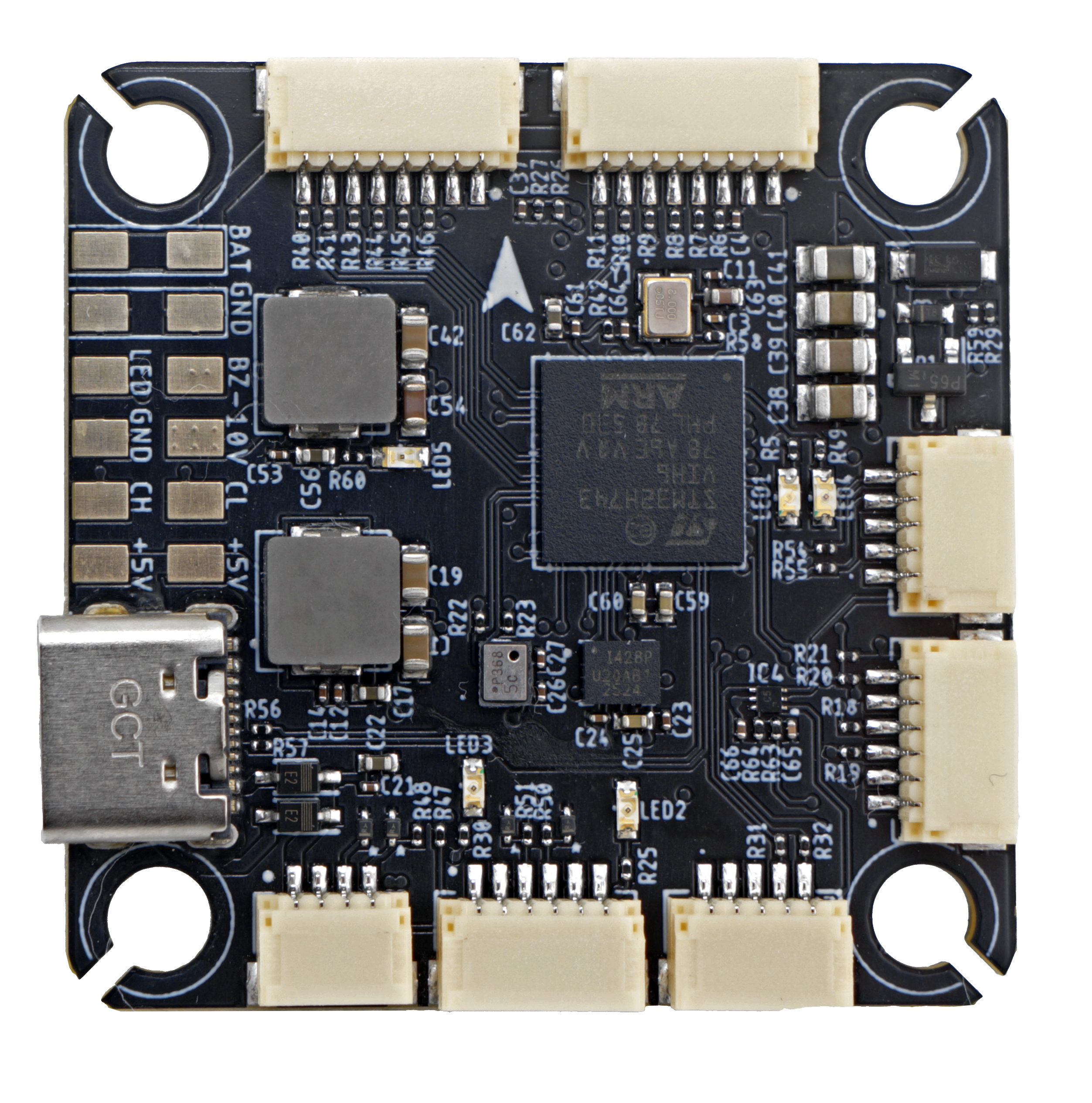
- Photos
- Notes
Target:
AEDROXH7
MCU:
STM32H743
IMU:
ICM42688P
OSD:
MAX7456
Baro:
DPS368
Blackbox:
128MB
Measurements:
Size: 38x38mm
Mounting: 30.5x30.5mm
Weight: 8.75g
Other Features
- SD Card Slot: No
- Onboard Receiver: No
- Hardware Inverter: No
- Bluetooth: No
- WiFi: No
- Onboard RGB LED: 1x Pad
- Camera Switch: Yes
Information
info
Input/Output
- USB Connector: USB Type-C
- Motor Outputs: 8x
- UARTs: 6x
- I2C: Yes
- SWD: Yes
- SPI: No
- 3.3V Output: Yes
- 4.5V (VBUS) Output: No
- 5V Output: 2.3A
- 10V Output: 2.3A (GPIO controlled)
- Current Sensor: Yes
- Analog RSSI Input: No
- LED Strip Output: Yes
- Buzzer Output: Yes
- GPIO: 2x
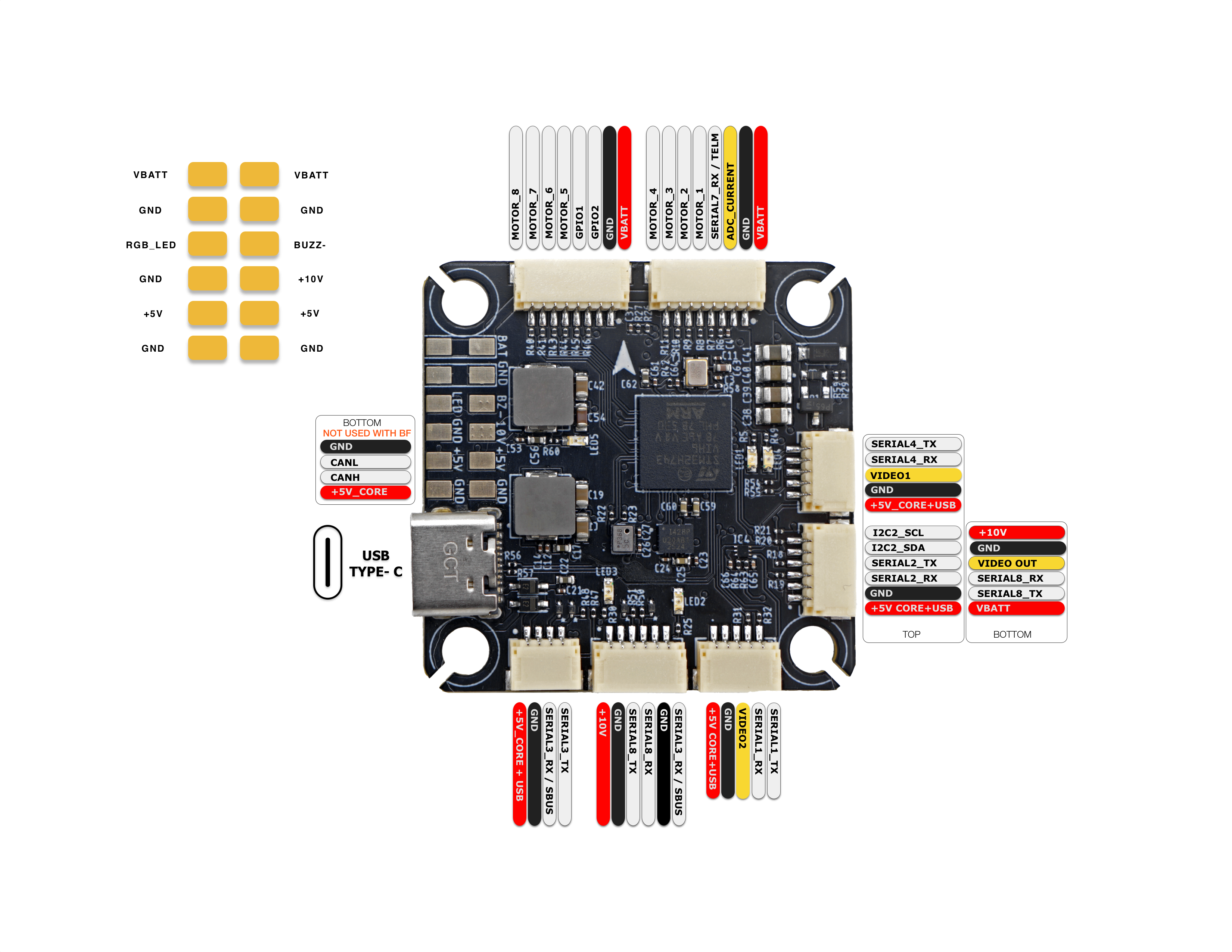
Connectors
Motors 1-4
| Pin # | Name | Label | Notes |
|---|---|---|---|
| 1 | Battery Voltage | VBATT | |
| 2 | Ground | GND | |
| 3 | Current | CUR | ADC Current |
| 4 | Telemetry | RX7 | ESC Telemetry |
| 5 | Signal 1 | Motor1 | |
| 6 | Signal 2 | Motor2 | |
| 7 | Signal 3 | Motor3 | |
| 8 | Signal 4 | Motor4 |
Motors 5-8
| Pin # | Name | Label | Notes |
|---|---|---|---|
| 1 | Battery Voltage | VBATT | |
| 2 | Ground | GND | |
| 3 | GPIO 2 | GPIO2 | PINIO |
| 4 | GPIO 1 | GPIO1 | PINIO |
| 5 | Signal 5 | Motor5 | |
| 6 | Signal 6 | Motor6 | |
| 7 | Signal 7 | Motor7 | |
| 8 | Signal 8 | Motor8 |
GPS/Compass
| Pin # | Name | Label | Notes |
|---|---|---|---|
| 1 | 5V | +5V | |
| 2 | Ground | GND | |
| 3 | UART 2 | RX2 | |
| 4 | UART 2 | TX2 | |
| 5 | I2C SDA | SDA | |
| 6 | I2C SCL | SCL |
CAM1
| Pin # | Name | Label | Notes |
|---|---|---|---|
| 1 | 5V | +5V | |
| 2 | Ground | GND | |
| 3 | Video 1 | Video1 | |
| 4 | UART 4 | RX4 | |
| 5 | UART 4 | TX4 |
CAM2
| Pin # | Name | Label | Notes |
|---|---|---|---|
| 1 | 5V | +5V | |
| 2 | Ground | GND | |
| 3 | Video 2 | Video2 | |
| 4 | UART 1 | RX1 | |
| 5 | UART 1 | TX1 |
HD VTX
| Pin # | Name | Label | Notes |
|---|---|---|---|
| 1 | 10V | +10V | |
| 2 | Ground | GND | |
| 3 | UART 8 | TX8 | |
| 4 | UART 8 | RX8 | |
| 5 | Ground | GND | |
| 6 | UART 3 | RX3 |
Receiver
| Pin # | Name | Label | Notes |
|---|---|---|---|
| 1 | 5V | +5V | |
| 2 | Ground | GND | |
| 3 | UART 3 | RX3 | |
| 4 | UART 3 | TX3 |
Analog VTX
| Pin # | Name | Label | Notes |
|---|---|---|---|
| 1 | 10V | +10V | |
| 2 | Ground | GND | |
| 3 | Video Out | Video Out | |
| 4 | UART 8 | RX8 | |
| 5 | UART 8 | TX8 | |
| 6 | Battery Voltage | VBATT |
Debug
| Pin # | Name | Label | Notes |
|---|---|---|---|
| 1 | 3.3V | 3V3 | Pad on bottom |
| 2 | SWDIO | IO | Pad on bottom |
| 3 | SWCLK | CK | Pad on bottom |
OSD Support
Analog OSD and HD OSD are sharing SERIAL8.
VTX Power Control
PINIO3 controls the VTX BEC output marked "10V". This power source is present on the HD VTX, Analog VTX ports and a solder pad. Setting this GPIO low will shut off voltage supply to these pins/pad.
Camera Switch
PINIO4 controls the camera switch. Setting this GPIO high will output the CAM1 stream, setting it low will output the CAM2 stream.