In-flight Adjustments
With Betaflight it's possible to make adjustments to various settings by using AUX channels from your transmitter while the aircraft is flying.
Warning
Changing settings during flight can make your aircraft unstable and crash if you are not careful.
Recommendations
- Always make adjustments while flying in a large open area.
- Make small adjustments and fly carefully to test your adjustment.
- Give yourself enough flying space and time to adjust to how your changes affect the behavior of the aircraft.
- Remember to set adjustment channel switches/pots to the center position before powering on your TX and your aircraft.
- If possible configure switch warnings on your transmitter for dedicated adjustment switches.
- A momentary 3 position switch is the best choice of switch for this - i.e. one that re-centers itself when you let go of it.
Overview
There are two modes of operation. The first supports adjusting settings by incrementing/decrementing them through use of an aux channel, typically a three position switch, where the middle position makes no change, and the other positions either increment or decrement the selected setting.
The other mode is Absolute mode where a pot (knob/slider) may be directly mapped and changes the selected setting to a value based on a center value, corresponding to mid-postion on the pot and a range of ± adjustment at the min/max positions of the pot.
Both modes utilise two channels to make an adjustment.
| Channel | Use |
|---|---|
| Range | This channel is used to enable an adjustment. When the channel is set to fall within the specified range, then the corresponding adjustment is enabled. This is similar to mode setting where a given mode is enabled when a channel is within a lower and upper range. |
| Adjustment | This channel is used to control the change to the specified setting |
Settings are not saved automatically, connect a GUI, refresh and save or save using stick position when disarmed. Powering off without saving will discard the adjustments.
Settings can be saved when disarmed using stick positions: Throttle Low, Yaw Left, Pitch Low, Roll Right.
Increment/Decrement mode
Up to 4 RX channels can be used to make different adjustments at the same time.
The adjustment the Adjustment Channel makes is controlled by the Range Channel.
The available adjustments are listed in this table.
Example scenarios: Up to 4 3-position switches or pots can be used to adjust 4 different settings at the same time. A single 2/3/4/5/6/x position switch can be used to make one 3 position switch adjust one setting at a time.
Any combination of switches and pots can be used. So you could have 6 POS switch.
Adjustment switches
The Adjustment switch is associated with the Adjustment Channel. The switch can be a ON-OFF-ON, POT or momentary ON-OFF-ON switch. The latter is recommended.
When the switch is returned to the center position the value will not be increased/decreased.
Each time you can press the switch high/low and then return it to the middle the value will change at least once, you do not have to wait before pressing the switch again if you want to increase/decrease at a faster rate. While the adjustment switch held is high/low, the adjustment function applies and increases/decreases the value being adjusted twice a second and the flight controller will beep shorter/longer, respectively. The system works similar to how a keyboard repeat delay works.
Hint: With OpenTX transmitters you can combine two momentary OFF-ON switches to control a single channel. You could make it so that a momentary switch on the left of your transmitter decreases the value and a momentary switch on the right increases the value. Experiment with your mixer!
Absolute mode
The adjustment is made where the Adjustment Channel is an Aux channel connected to a pot (knob/slider). This provides an easier approach than using the Increment/Decrement mode as it is easier to keep track of the setting.
Note that if the same pot is used as the Adjustment Channel to make multiple adjustments, there is a risk of a jump in values of the second setting when switching from the first if the pot is not centered. To avoid this it is recommended that if adjusting two different settings using the same pot, a three position switch be used for the Range Channel, with neither setting associated with the middle position.
Configuration
The CLI command adjrange is used to configure adjustment ranges.
12 adjustment ranges can be defined.
Show the current ranges using:
adjrange
Configure a range using:
adjrange <index> 0 <range channel> <range start> <range end> <adjustment function> <adjustment channel>
| Argument | Value | Meaning |
|---|---|---|
| Index | 0 - 29 | Select the adjustment range to configure |
| 0 | 0 | Used as slot before Betaflight 4.1 |
| Range Channel | 0 based index, AUX1 = 0, AUX2 = 1 | The AUX channel to use to select an adjustment for a switch/pot |
| Range Start | 900 - 2100. Steps of 25, e.g. 900, 925, 950... | Start of range |
| Range End | 900 - 2100 | End of range |
| Adjustment function | See Adjustment functions table | |
| Adjustment channel | 0 based index, AUX1 = 0, AUX2 = 1 | The channel that is controlled by a 3 Position switch/Pot |
| Center Value | If this is non-zero then Absolute Mode is used for this range otherwise Increment/Decrement Mode is used. In Absolute Mode this value is the value which will be assigned to the setting when the Adjustment Channel is set to mid-position. | |
| Scale Value | This specifies the amount that will be subtracted/added to the center value when the Adjustment Channel is at min/max respectively. |
Range Start/End values should match the values sent by your receiver.
The Range Channel and the Adjustment Channel can be the same channel. This is useful when you want a single 3 Position switch to be dedicated to a single adjustment function regardless of other switch positions.
The adjustment function is applied to the adjustment channel when range channel is between the range values. The adjustment is made when the adjustment channel is in the high or low position. high = mid_rc + 200, low = mid_rc - 200. by default this is 1700 and 1300 respectively.
Adjustment functions
| Value | Adjustment | Notes |
|---|---|---|
| 0 | None | |
| 1 | RC RATE | Step / absolute setting |
| 2 | RC_EXPO | Step / absolute setting |
| 3 | THROTTLE_EXPO | Step / absolute setting |
| 4 | PITCH_ROLL_RATE | Step / absolute setting |
| 5 | YAW_RATE | Step / absolute setting |
| 6 | PITCH_ROLL_P | Step / absolute setting |
| 7 | PITCH_ROLL_I | Step / absolute setting |
| 8 | PITCH_ROLL_D | Step / absolute setting |
| 9 | YAW_P | Step / absolute setting |
| 10 | YAW_I | Step / absolute setting |
| 11 | YAW_D | Step / absolute setting |
| 12 | RATE_PROFILE | Switch between 3 or 6 rate profiles (uses rate_6pos_switch setting) |
| 13 | PITCH_RATE | Step / absolute setting |
| 14 | ROLL_RATE | Step / absolute setting |
| 15 | PITCH_P | Step / absolute setting |
| 16 | PITCH_I | Step / absolute setting |
| 17 | PITCH_D | Step / absolute setting |
| 18 | ROLL_P | Step / absolute setting |
| 19 | ROLL_I | Step / absolute setting |
| 20 | ROLL_D | Step / absolute setting |
| 21 | RC_RATE_YAW | Step / absolute setting |
| 22 | PITCH_ROLL_F | Step / absolute setting |
| 23 | FEEDFORWARD_TRANSITION | Step / absolute setting |
| 24 | HORIZON_STRENGTH | Select the horizon strength |
| 25 | PID_AUDIO | Select the PID value to be turned into tones |
| 26 | PITCH_F | Step / absolute setting |
| 27 | ROLL_F | Step / absolute setting |
| 28 | YAW_F | Step / absolute setting |
| 29 | OSD_PROFILE | Switch between 3 OSD profiles |
| 30 | LED_PROFILE | Switch between the RACE / BEACON / STATUS LED strip profiles |
Examples
Example 1 - 3 Position switch used to adjust pitch/roll rate
adjrange 0 0 3 900 2100 4 3 0 0
explained:
- configure adjrange 0 so that when aux4 (3) in the range 900-2100 then use adjustment 4 (pitch/roll rate) when aux 4 (3) is in the appropriate position.
- note that Center/Scale values are both zero, so this range will use increment/decrement mode.
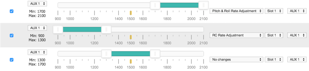
Example 2 - 2 Position switch used to enable adjustment of RC rate via a 3 position switch
adjrange 1 0 0 900 1700 0 2 0 0
adjrange 2 0 0 1700 2100 1 2 0 0
explained:
- configure adjrange 1 so that when aux1 (0) in the range 900-1700 then do nothing (0) when aux 3 (2) is in any position.
- configure adjrange 2 so that when aux1 (0) in the range 1700-2100 then use adjustment rc rate (1) when aux 3 (2) is in the appropriate position.
- note that Center/Scale values are both zero, so this range will use increment/decrement mode.
Without the entire range of aux1 being defined there is nothing that would stop aux 3 adjusting the pitch/roll rate once aux 1 wasn't in the higher range.
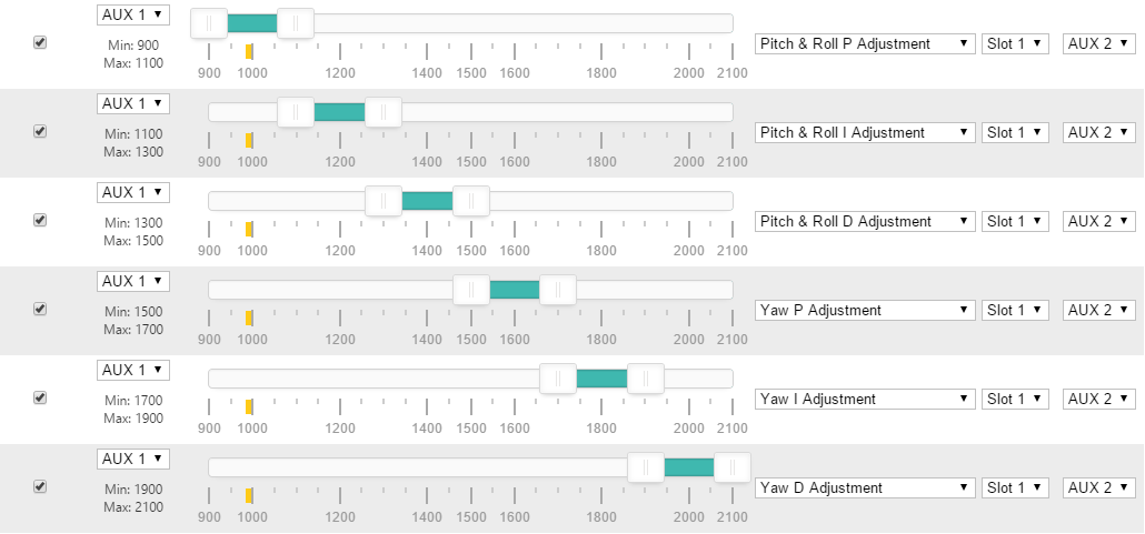
Example 3 - 6 Position switch used to select PID tuning adjustments via a 3 position switch
adjrange 3 0 1 900 1150 6 3 0 0
adjrange 4 0 1 1150 1300 7 3 0 0
adjrange 5 0 1 1300 1500 8 3 0 0
adjrange 6 0 1 1500 1700 9 3 0 0
adjrange 7 0 1 1700 1850 10 3 0 0
adjrange 8 0 1 1850 2100 11 3 0 0
explained:
- configure adjrange 3 so that when aux2 (1) in the range 900-1150 then use adjustment Pitch/Roll P (6) when aux 4 (3) is in the appropriate position.
- configure adjrange 4 so that when aux2 (1) in the range 1150-1300 then use adjustment Pitch/Roll I (7) when aux 4 (3) is in the appropriate position.
- configure adjrange 5 so that when aux2 (1) in the range 1300-1500 then use adjustment Pitch/Roll D (8) when aux 4 (3) is in the appropriate position.
- configure adjrange 6 so that when aux2 (1) in the range 1500-1700 then use adjustment Yaw P (9) when aux 4 (3) is in the appropriate position.
- configure adjrange 7 so that when aux2 (1) in the range 1700-1850 then use adjustment Yaw I (10) when aux 4 (3) is in the appropriate position.
- configure adjrange 8 so that when aux2 (1) in the range 1850-2100 then use adjustment Yaw D (11) when aux 4 (3) is in the appropriate position.
- note that Center/Scale values are both zero, so this range will use increment/decrement mode.
Example 4 - Use a single 3 position switch to change between 3 different rate profiles
adjrange 11 0 3 900 2100 12 3 0 0
explained:
- configure adjrange 11 so that when aux4 (3) in the range 900-2100 then use adjustment Rate Profile (12) when aux 4 (3) is in the appropriate position.
- note that Center/Scale values are both zero, so this range will use increment/decrement mode.
When the switch is low, rate profile 0 is selected. When the switch is medium, rate profile 1 is selected. When the switch is high, rate profile 2 is selected.
Example 5 - Use a single switch to enable absolute setting of Roll/Pitch P terms from two pots
adjrange 0 0 4 1450 1550 18 0 40 10
adjrange 1 0 4 1450 1550 15 1 58 20
explained:
- note that Center value is non-zero, so this range will use absolute mode.
- configure adjrange 0 so that when aux5 (3) in the range 1450-1550 then use aux 1 (0) to adjust Roll P Adjustment (18) such that the value will be 40 with the pot centered and 30/50 at min/max.
- configure adjrange 1 so that when aux5 (3) in the range 1450-1550 then use aux 2 (0) to adjust Pitch P Adjustment (15) such that the value will be 58 with the pot centered and 38/78 at min/max.
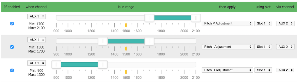
Example 6 - Use a single switch to enable absolute setting of Roll/Pitch P/I/D terms from three pots, selected using a single switch
adjrange 0 0 4 950 1050 18 0 40 20
adjrange 1 0 4 950 1050 19 1 107 53
adjrange 2 0 4 950 1050 20 2 76 38
adjrange 3 0 4 1950 2050 15 0 63 16
adjrange 4 0 4 1950 2050 16 1 138 69
adjrange 5 0 4 1950 2050 17 2 66 33
explained:
- note that Center value is non-zero, so this range will use absolute mode.
This assigns pots aux 1, aux 2, and aux 3 respectively to control P, I and D settings with the pots at mid-position giving the default P/I/D values and providing a range of adjustment of +/- 50%. When the aux 5 switch is in one end position then roll P/I/D will be adjusted and when the aux 5 switch is in the other end position, pitch P/I/D will be adjusted. In the aux 5 switch middle position nether will be adjusted. Thus one could center the pots, select roll on aux 5 and then adjust the P/I/D values in flight. Then land, move the aux 5 switch to center, center the pots, select pitch on the switch and then again adjust P/I/D in flight.
Configurator examples
Note that the configurator does not currently support the Center/Scale values, however it may still be used to setup the ranges and then the CLI may be used to set the Center/Scale values.
The following 5 images show valid configurations. In all cases the entire usable range for the Range Channel is used.


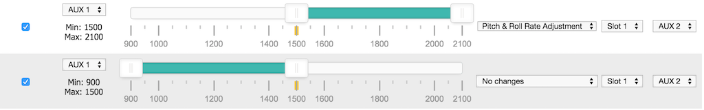
The following examples shows incorrect configurations - the entire usable range for the Range Channel is not used in both cases.
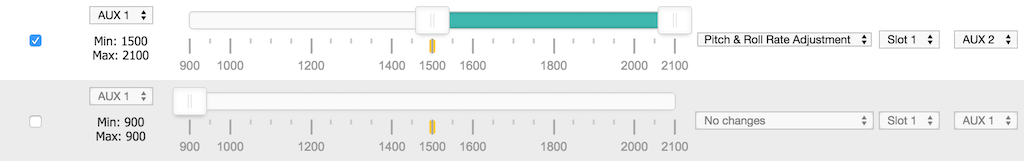
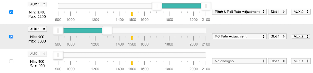
In the following example, the incorrect configuration (above) has been corrected by adding a range that makes 'No changes'.